This article is part of a series of articles about using DGN line styles in a .dwg file. For the previous article, see Part 2.
Autodesk® AutoCAD® linetypes, which are the default linetypes for a .dwg database, have limitations with linetype content. In addition to dashes and dots, they support only text and SHX shape embedding into linetype patterns. DGN line styles provide the ability to embed entire blocks with any content inside the linetype pattern and provide many additional customization options. In this article we look at inserting symbols (blocks) into DGN line styles embedded in a .dwg database.
Creating symbol components
Symbol components represent a block reference in terms of a DGN line style and provide parameters to set up geometry data behavior.
To start working with symbol components, include a header with the OdDbLSSymbolComponent class declaration:
#include "DgnLS/DbLSSymbolComponent.h"
Creating symbol components is very similar to creating other DGN line style components:
// Create symbol component for first block
OdDbLSSymbolComponentPtr pSymComponent = OdDbLSSymbolComponent::createObject();
pSymComponent->setComponentType(kLSSymbolComponent);
pSymComponent->setDescription(OD_T("DemoDgnSymbol1"));
pSymComponent->setComponentUID(dgnLS_UID);
Now we require a .dwg block to connect it with the created symbol component. For example, let’s use the following functions to generate a new block and attach it to a .dwg database:
static OdDbHelixPtr createHelix(OdGePoint3d location, double radius)
{
  OdDbHelixPtr helPtr = OdDbHelix::createObject();
  helPtr->setStartPoint(location - OdGeVector3d::kZAxis);
  helPtr->setConstrain(OdDbHelix::kTurns);
  helPtr->setBaseRadius(radius);
  helPtr->setTopRadius(radius / 5);
  helPtr->setTurns(4.0);
  helPtr->setAxisVector(OdGeVector3d::kZAxis);
  helPtr->createHelix();
  return helPtr;
}

static OdDbBlockTableRecordPtr createSegmentBlock()
{ const double fBlockScale = 1.0 / 1000.0;
  OdDbBlockTableRecordPtr btrPtr = OdDbBlockTableRecord::createObject();
  btrPtr->appendOdDbEntity(createHelix(OdGePoint3d(-fBlockScale, -fBlockScale, 0.0), fBlockScale));
  btrPtr->appendOdDbEntity(createHelix(OdGePoint3d( fBlockScale, -fBlockScale, 0.0), fBlockScale));
  btrPtr->appendOdDbEntity(createHelix(OdGePoint3d(-fBlockScale,  fBlockScale, 0.0), fBlockScale));
  btrPtr->appendOdDbEntity(createHelix(OdGePoint3d( fBlockScale,  fBlockScale, 0.0), fBlockScale));
  btrPtr->setName(OD_T("4helix"));
  return btrPtr;
}

static OdDbObjectId appendBlock(OdDbDatabase *pDb, OdDbBlockTableRecordPtr btrPtr)
{
  return OdDbBlockTable::cast(pDb->getBlockTableId().openObject(OdDb::kForWrite))->add(btrPtr);
}
After executing this code, we have a new block named “4helix” in the database, and the block contains four helix entities inside it:
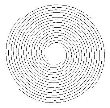
Take into account that we use a [1.0 / 1000.0] scale for geometry inside the block. This is required because AutoCAD ignores symbol scale that is set in the symbol component, and as a result it expects that block content is pre-scaled using the 1/1000 factor.
Now we can attach the created block to our symbol component and register this component in the DGN line styles dictionary:
// Attach block to symbol component
pSymComponent->setBlockTableRecord(::appendBlock(pDb, ::createSegmentBlock()));

// Add component into LineStyles dictionary
pDict->setAt(OD_T("DemoDgnSymbolForSegment"), pSymComponent);
Similarly in this example we create a second symbol component that is used to highlight line curve endings:
// Create symbol component for second block
pSymComponent = OdDbLSSymbolComponent::createObject();
pSymComponent->setComponentType(kLSSymbolComponent);
pSymComponent->setDescription(OD_T("DemoDgnSymbol2"));
::oddbDgnLSIncrementUID(dgnLS_UID);
pSymComponent->setComponentUID(dgnLS_UID);
This code is almost the same as the previous symbol component creation, but it contains one additional call to the oddbDgnLSIncrementUID function. Since this is preferred, that all components contain different UIDs, we can modify the previously generated UID using the oddbDgnLSIncrementUID function call. This is much simpler than generating a completely new UID. This helper function is declared in the "DgnLS/DbLSMisc.h" header file.
The function that we use to create arrow-like geometry inside the block is the following:
static OdDbBlockTableRecordPtr createArrowBlock()
{
  const double fBlockScale = 1.0 / 1000.0;
  OdDbPolylinePtr pPl = OdDbPolyline::createObject();
  pPl->addVertexAt(0, OdGePoint2d(-fBlockScale, -fBlockScale));
  pPl->addVertexAt(1, OdGePoint2d(-fBlockScale,  fBlockScale));
  pPl->addVertexAt(2, OdGePoint2d( fBlockScale,  0.0));
  pPl->setClosed(true);
  OdDbBlockTableRecordPtr btrPtr = OdDbBlockTableRecord::createObject();
  btrPtr->appendOdDbEntity(pPl);
  btrPtr->setName(OD_T("arrow"));
  return btrPtr;
}
It generates polyline geometry:
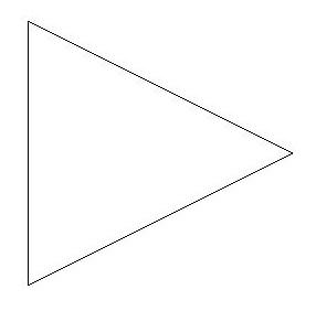
As for the previously generated block, we’ve used the 1/1000 scale for block content.
And now finally, attach the created block to the symbol component and attach the symbol component to the DGN line style dictionary:
// Attach block to symbol component
pSymComponent->setBlockTableRecord(::appendBlock(pDb, ::createArrowBlock()));

// Add component into LineStyles dictionary
pDict->setAt(OD_T("DemoDgnSymbolForLineEnd"), pSymComponent);
The next article in this series describes working with point line style components.