Rendering
FillPattern rendering is performed when rendering a corresponding shell if the OdGiFill traits attribute is supplied. As described in a previous article, OdGiFill is supplied by an OdBmFillPatternElem::subSetAttributes(OdGiDrawableTraits* pDrwTraits) call if an existing OdBmFace->OdBmGFilling->PatternId is present. OdGiFill represents the hatch data needed for a FillPattern to be rendered, which is not enough. To render the pattern correctly, OdGiFaceData and OdGiMapperItemEntry are also required.
Schematically the process can be broken down into the following steps:
1) Determine the pattern scale.
double patternScal = 1.0;
if (pHatch->isDraft())
{
  if (m_pDrawCtx)
  {
    patternScal = m_pDrawCtx->annotationScale();
  }
}
Draft patterns are view-scale dependent. So it should be obtained (via the corresponding Portable Extension) and taken into account.
2) Determine if a mapper should be used.
OdGiMapperItemEntryPtr pCurrentMapper;
if (pMapper)
{
  OdGiMapper::Projection proj = pMapper->mapper().projection();
  if (proj == OdGiMapper::kCylinder || proj == OdGiMapper::kSphere)
  {
    pCurrentMapper = pMapper;
  }
}
If the face requires non-planar texture mapping, FillPattern should be processed the same way as the texture by a mapper.
3) Calculate the projecting plane and project all the face vertices to the plane.
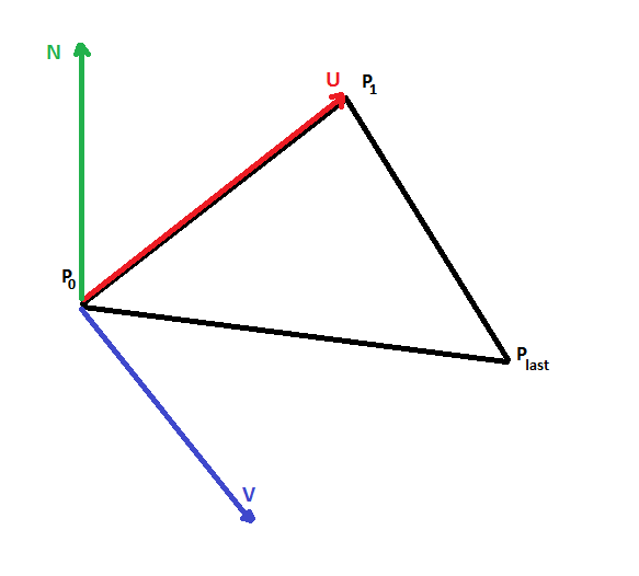
The projecting plane is represented by point P0, two orthogonal vectors U,V, and is calculated from the three points (P0, P1, Pn-1) of the given face. Projecting the plane is required because hatch processing is done in 2D space.
4) Calculate texture mapping transform, if required.
OdGePoint3d origin;
OdGeVector3d U, V;
plane.get(origin, U, V);

OdGiMapperItemEntry::MapInputTriangle pts;
pts.inPt[0] = origin;
pts.inPt[1] = origin + U;
pts.inPt[2] = origin + V;

OdGiMapperItemEntry::MapOutputCoords res;
pCurrentMapper->mapCoords(pts, res);

OdGeVector2d newU = res.outCoords[1] - res.outCoords[0];
OdGeVector2d newV = res.outCoords[2] - res.outCoords[0];

OdGeMatrix2d trf;
trf[0][0] = new.x;
trf[0][1] = new.y;
trf[1][0] = new.x;
trf[1][1] = new.y;
If a mapper is presented, a 2D mapping transform should be used to map the pattern to a face correctly.
5) Correct the hatch data with a face-specific offset and angle.
OdGePoint2d faceFillOrigin = pFaceData->fillOrigins()[faceIndex];
OdGeVector2d faceFillDirection = pFaceData->fillDirections()[faceIndex];

patLine.m_basePoint += faceFillOrigin.asVector();
patLine.m_dLineAngle += faceFillDirection.angle();
A face-specific offset and angle are supplied through OdGiFaceData and have to be taken into account to draw the pattern correctly.
6) Send the prepared data to the hatch drawing procedure.
The procedure outputs hatch lines in 2D space, so they have to be transformed back to 3D space and then drawn.
bool dash(const OdGePoint2d& _start, const OdGePoint2d& _end)
{
  OdGePoint2d start = m_Trf * _start;
  OdGePoint2d end = m_Trf * _end;

  OdGePoint3d points[2];

  points[0] = m_PlaneOrigin + start.x * m_PlaneU + start.y * m_PlaneV;
  points[1] = m_PlaneOrigin + end.x * m_PlaneU + end.y * m_PlaneV;

  m_pSimplifier->polylineProc(2, points);
  return true;
}