This article contains an example of using the geometry sectioning callback. It is the second article in a series; for the first article, which contains more details, see Part 1.
For our example, we’ll use the following model with four 3D objects:
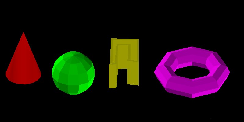
Each object is placed on its own layer with a different color:
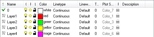
We will use the layer numbers from layer names in our example. First implement your own class inherited from the OdGiClippedGeometryOutputCallback class that will contain our callback function implementation:
struct ClippingCallback : public OdGiClippedGeometryOutputCallback
{
  static const bool pSectVis[4], pCutVis[4];
  static const OdUInt16 pSectClr[4], pCutClr[4];

  virtual bool clippedGeometryOutputCallbackProc(OdGiClippedGeometryOutput &pGeomOutput, const OdGiConveyorContext &pDrawContext)
  {
    OdDbEntity* pEnt = OdDbEntity::cast(pDrawContext.currentDrawable());
    if (pEnt)
    {
      const OdString layer = pEnt->layer();
      if (layer.left(5) == OD_T("Layer"))
      {
        const int lrNum = int(layer.getAt(5) - '0') - 1;
        const bool bCutting = pGeomOutput.isA() == OdGiCuttedGeometryOutput::desc();
        const bool *pVis = (bCutting) ? pCutVis : pSectVis;
        const OdUInt16 *pClr = (bCutting) ? pCutClr : pSectClr;
        pGeomOutput.setTraitsOverrideFlags(pGeomOutput.traitsOverrideFlags() | OdGiSubEntityTraitsChangedFlags::kColorChanged);
        pGeomOutput.traitsOverrides().setColor(pClr[lrNum]);
        return pVis[lrNum];
      }
    }
    return true;
  }
  ClippingCallback() {}
};
In our clippedGeometryOutputCallbackProc() method implementation, we invoke four static arrays:
- bool pSectVis[4] — Contains visibilities for section geometry.
- bool pCutVis[4] — Contains visibilities for cut geometry.
- OdUInt16 pSectClr[4] — Contains color indexes for section geometry.
- OdUInt16 pCutClr[4] — Contains color indexes for cut geometry.
We use the layer number as an index for these arrays. Since we will invoke this callback not only for section output geometry but for cut geometry output too, we check whether pGeomOutput is cut geometry output or not, and use the appropriate array after that to change the geometry color and return the geometry visibility flag.
Construct our section/cut geometry callback and set it together with the geometry clipping boundary:
// Construct our callback object
  OdGiClippedGeometryOutputCallbackPtr pSectionCallback = OdRxObjectImpl<ClippingCallback>::createObject();
  // Construct clipping boundary with section planes
  OdGiPlanarClipBoundary bnd; bnd.setClipPlanes(clipPlanes);
  bnd.setSectionGeometryOutput(OdGiSectionGeometryOutput::createObject());
  { OdGiCuttedGeometryOutputPtr pTraitsSets = OdGiCuttedGeometryOutput::createObject();
    pTraitsSets->setTraitsOverrideFlags(OdGiSubEntityTraitsChangedFlags::kTransparencyChanged);
    pTraitsSets->traitsOverrides().setTransparency(OdCmTransparency(0.5));
    bnd.setCuttedGeometryOutput(pTraitsSets);
  }
  // Setup our callback object
  bnd.sectionGeometryOutput()->setGeometryProcessingCallback(pSectionCallback);
  bnd.cuttedGeometryOutput()->setGeometryProcessingCallback(pSectionCallback);
  // Setup viewport clipping
  OdGiClipBoundary emptyBoundary;
  ::odgiEmptyClipBoundary(emptyBoundary);
  pGsView->setViewport3dClipping(&emptyBoundary, &bnd);
This code is almost that same as code examples from previous section article and cut geometry article. Here we additionally set a transparency override to make cut geometry semi-transparent, otherwise we will not see geometry sections.
First let’s set geometry visibility to true for all layers to make all section and cut geometry visible. And set different colors for each layer.
const bool ClippingCallback::pSectVis[4] = { true, true, true, true };
const bool ClippingCallback::pCutVis[4] = { true, true, true, true };
const OdUInt16 ClippingCallback::pSectClr[4] = { 4, 32, 220, 81 };
const OdUInt16 ClippingCallback::pCutClr[4] = { 231, 20, 171, 9 };
The generated image looks like this:
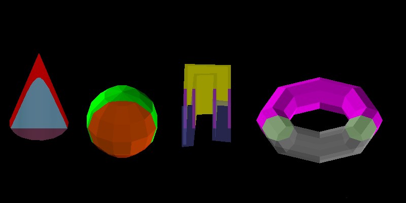
As we can see, for all objects, section and cut geometry were generated with different colors. Now we can additionally disable types of geometry (cut or section) for some objects:
const bool ClippingCallback::pSectVis[4] = { true, false, false, true };
const bool ClippingCallback::pCutVis[4] = { true, true, false, false };
const OdUInt16 ClippingCallback::pSectClr[4] = { 4, 32, 220, 81 };
const OdUInt16 ClippingCallback::pCutClr[4] = { 231, 20, 171, 9 };
The resulting image is something like this:
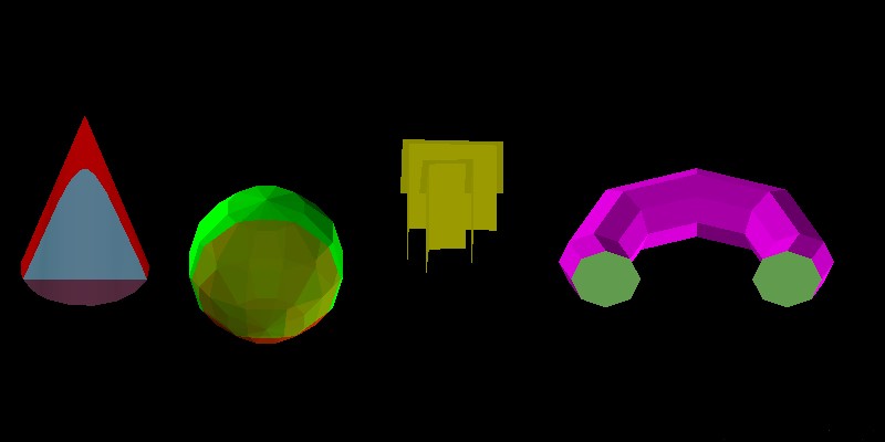
As you can see, the first object (cone) is drawn with section and cut geometry, because they are both enabled for it. The second object (sphere) is drawn without section geometry, but with enabled cut geometry. The third object is clipped, but both section and cut geometry output is disabled for it. And the last object (torus) is drawn only with section geometry.
This simple example shows how a clipping geometry callback can be used to configure output geometry behavior for different graphics scene objects.
Conclusion
The clipped geometry output callback provides a simple way to configure section and cut geometry output behaviors, depending on database object specifics. This flexible functionality provides the ability to configure an entire clipped graphics scene for all software needs.