This article is part of a series about setting the quality of TrueType font text. For the previous article, see Part 1.
In the previous article we described changing the quality of TrueType font text using a constant setting. This article describes changing the quality dynamically using TTF PolyDraw mode.
Dynamic TTF PolyDraw mode
TTF PolyDraw mode avoids tessellation of text characters until actual tessellation data is required by a renderer or ODA vectorization framework client. This means that instead of pre-tessellated geometry, the font manager passes Bezier curve information to the geometry conveyor, so client code can tessellate text using any quality that is required for TrueType font processing. For example, ODA vectorization modules can tessellate such text characters with currently available deviation, so the text quality is good at any zoom level. In comparison, the constant text quality font manager doesn’t require to keep large arrays of pre-tessellated vertices in system memory, so font characters are tessellated with the required quality when preparing the graphics cache instead.
Using TTF PolyDraw mode in the OdaMfcApp example application
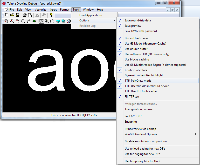
To enable TTF PolyDraw mode in the OdaMfcApp example application, choose Tools -> Options -> TTF: PolyDraw mode:
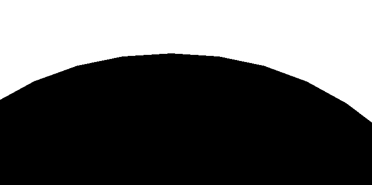
Zoom out to make text far away:

Call the REGEN command to update the graphics cache, then zoom to text:

When text quality becomes too rough, call the REGEN command again to update the graphics cache with better quality:

Next zoom to the text to make it closer:

And at any zoom level, we can call the REGEN command to update the graphics cache with optimal quality for the current zoom level:

Enabling TTF PolyDraw mode for a .dwg database
To enable TTF PolyDraw mode for a .dwg database, you can simply call the OdGiContextForDbDatabase::setTtfPolyDrawMode() method (see ODA Documentation, login required):
pGiContextForDwgDatabase->setTtfPolyDrawMode(true);
Enabling TTF PolyDraw mode in general
The general way to enable TTF PolyDraw mode (which works for all ODA products based on Kernel SDK) is to override the OdGiContext::ttfPolyDraw() method (see ODA documentation, login required). OdGiContext is invoked by all ODA vectorization processes, so the ttfPolyDraw() method can be used to enable TTF PolyDraw mode for any of them. By default, the ttfPolyDraw() method returns false. Each ODA product, Drawings (for both .dwg and .dgn files), BIM, and PRC, have their own implementations of OdGiContext; for example in Drawings SDK this class is called OdGiContextForDbDatabase. Each OdGiContext implementation can have their own override and implementation of the ttfPolyDraw() method as in OdGiContextForDbDatabase, but there is no problem to override this method once more in its own class inherited from the required OdGiContext implementation, and pass it to the ODA vectorization framework.
Support TTF PolyDraw data in a vectorization conveyor
TrueType font text characters are typically drawn using shell geometry primitives, which are accessible in the geometry conveyor using the shellProc method override. If TTF PolyDraw mode is enabled, the ttfPolyDrawProc geometry conveyor method is called for TrueType font characters instead of shellProc. If client code doesn’t override the ttfPolyDrawProc method, it is handled by the OdGiGeometrySimplifier::ttfPolyDrawProc method implementation and is converted into shellProc geometry primitives with the currently set deviation (see ODA Blog for more details).
Client code can override the OdGiConveyorGeometry::ttfPolyDrawProc method to process PolyDraw data independently. For example this is done in the TXTEXP command to tessellate TrueType font text contours with specific precision.
void ttfPolyDrawProc(OdInt32 numVertices, const OdGePoint3d* vertexList,
OdInt32 faceListSize, const OdInt32* faceList,
const OdUInt8* pBezierTypes, const OdGiFaceData* pFaceData = 0)
Refer to .\main\Drawing\Examples\ExCommands\ExTxtExp.cpp, TXTEXP command source code. The ttfPolyDrawProc method contains arguments similar to shellProc, but it is extended by the pBezierTypes values array. The number of entries in this array is similar to the number of vertices passed into the ttfPolyDrawProc method. The following table describes values that can be present in this array:
| Value (bit flags) | Description |
|---|---|
| 1 (Closed Figure) | This value is typically combined with the “Line To” or “Bezier To” flag and means that the currently drawn figure must be closed. In this case, the next (if present) value represents the first point of the next figure. |
| 2 (Line To) | Simple line drawn from a previous vertex to this vertex. |
| 4 (Bezier To) | Control point of a Bezier curve. Bezier curves consist of four vertices, the last three of them are marked by this flag. |
| 6 (Move To) | Marks the first point of a disjoint figure. |
We can formalize this bit flag as a C++ enumeration:
enum pdFlags
{
kpdCloseFigure = 0x01,
kpdLineTo      = 0x02,
kpdBezierTo    = 0x04,
kpdMoveTo      = 0x06
};
The following piece of simplified code from the TXTEXP command example demonstrates how this array of flags can be processed to create a set of polylines:
int nVerts = 0; // Number of vertexes currently processed for this polyline
OdDbPolylinePtr pPl; // Currently processing polyline
int bzCnt = 0; // Number of points collected for Bezier curve
OdGePoint3d bzSpl[4]; // Collected Bezier curve points
for (OdInt32 i = 0; i < numVertices; i++)
{
if (pBezierTypes[i] == kpdMoveTo)
{ // Create new polyline and add first vertex
pPl = OdDbPolyline::createObject();
nVerts = 0;
pPl->addVertexAt(nVerts++, vertexList[i].convert2d());
}
else
{
if (GETBIT(pBezierTypes[i], kpdLineTo))
{ // Add line segment
pPl->addVertexAt(nVerts++, vertexList[i].convert2d());
}
else if (GETBIT(pBezierTypes[i], kpdBezierTo))
{
bzCnt++; // Collect next Bezier curve vertex
bzSpl[bzCnt] = vertexList[i];
if (bzCnt == 3)
{
const int nSegs = 8; // Set number of segment for Bezier curve tessellation
// This is a sequence of 3 bezierTo points + previous point, so when we collect 3rd bezierTo,
// we could construct cubic spline based on 4 points.
. . .
// Add last vertex
pPl->addVertexAt(nVerts++, vertexList[i].convert2d());
bzCnt = 0;
}
}
}
if (GETBIT(pBezierTypes[i], kpdCloseFigure))
{
appendEntity(pPl); // Add currently processed polyline
// Create next polyline for processing and add first vertex
pPl = OdDbPolyline::createObject();
nVerts = 0;
pPl->addVertexAt(nVerts++, vertexList[i].convert2d());
}
}
This piece of code uses a classic algorithm to tessellate an accumulated cubic spline that consists of four vertices to the required number of polyline segments:
const int nSegs = 8; // Set number of segments for Bezier curve tessellation
// This is a sequence of 3 bezierTo points + previous point, so when we collect 3rd bezierTo,
// we could construct cubic spline based on 4 points.
pPl->getEndPoint(bzSpl[0]); // Get previous point for tessellation
double d = 1. / nSegs;
for (int n = 1; n < nSegs; n++)
{
double t = d * n;
double u = 1.0 - t;
double tt = t * t, uu = u * u;
double uuu = uu * u, ttt = tt * t;
double uut3 = uu * t * 3, utt3 = u * tt * 3;

pnt = OdGePoint3d(
bzSpl[0].x * uuu + bzSpl[1].x * uut3 + bzSpl[2].x * utt3 + bzSpl[3].x * ttt,
bzSpl[0].y * uuu + bzSpl[1].y * uut3 + bzSpl[2].y * utt3 + bzSpl[3].y * ttt,
bzSpl[0].z * uuu + bzSpl[1].z * uut3 + bzSpl[2].z * utt3 + bzSpl[3].z * ttt);
pPl->addVertexAt(nVerts++, pnt.convert2d());
}
// Add last vertex
pPl->addVertexAt(nVerts++, vertexList[i].convert2d());
bzCnt = 0;
After execution of this code, we have a set of polylines on output which represent TrueType font character contours with given quality (tessellation precision).
This is the last article in the series about adjusting text quality of TrueType font text.