To create a boundary representation model (for example, a cone) with trimming loops, use the following steps:
1. Generate a PRC file with B-Rep topology. Examples of creating such files are in OdPrcCreate and are described in the PRC documentation in Working with Representation Entities (login required).
2. Add a connex and shell to BrepData:
OdPrcConnexPtr pCurConnex = OdPrcConnex::createObject();
brepData->addConnex(pCurConnex);
OdPrcShellPtr pCurShell = OdPrcShell::createObject();
pCurConnex->addShell(pCurShell);
3. Create a face and cone surface with a transformation, for example, the height of the cone from 0.001799999999999952 to infinity:
OdPrcFacePtr pCurFace = OdPrcFace::createObject();
OdPrcConePtr pPrcCone = OdPrcCone::createObject();
OdGeMatrix3d matr;
OdGePoint3d orPnt(0.00848600820104306,0.01503506648794965,0.0162750000534332);
OdGeVector3d x(1,0,1.40002853754603e-008);
OdGeVector3d y(0,-1,0);
OdGeVector3d z(x.crossProduct(y));
matr.setCoordSystem(orPnt,x,y,z);
OdPrcTransformation3d trans;
trans.set(matr);
pPrcCone->setTransformation(&trans);
pPrcCone->setBottomRadius(0.0018);
pPrcCone->setSemiAngle(0.7853981633974617);
pPrcCone->setUVParameterization(OdPrcUVParameterization(0,Oda2PI,-0.001799999999999952,12345));
4. Create a circle for the first trimming loop:
OdPrcCircle3dPtr crvCircle = OdPrcCircle3d::createObject();
OdPrcContentCurve &crvContent = crvCircle->contentCurve();
// set name
crvContent.baseGeometry().name().setName(L"named circle in crvContent");
// add some data to params
OdPrcParameterization curveParams(0, Oda2PI);
crvCircle->setParameterization( curveParams );
// can add transformation if needed here
OdGeMatrix3d matr;
OdGePoint3d orPnt(0.008486008203843119,0.01503506648794965,0.0160750000534332);
OdGeVector3d x(1,0,1.40002853754603e-008);
OdGeVector3d y(0,-1,0);
OdGeVector3d z(x.crossProduct(y));
matr.setCoordSystem(orPnt,x,y,z);
OdPrcTransformation3d transform;
transform.set(matr);
crvCircle->setTransformation(&transform);
// TBD
crvCircle->setRadius(0.002);
5. Create the first edge and set the geometry created in step 4:
OdPrcEdgePtr edge = OdPrcEdge::createObject();
edge->contentWireEdge().curve() = crvCircle;
6. Create the first CoEdge and set the edge created in step 5. A co-edge is a directed edge. The two co-edges are related to an edge point in the same or opposite direction along the edge. Each co-edge is associated with a loop of one of the two neighboring/adjacent faces.
OdPrcCoEdgePtr coEdge = OdPrcCoEdge::createObject();
coEdge->setEdge(edge);
7. Set the orientation of the first CoEdge to indicate the relative orientation of the loop. kOpposite is the opposite orientation of the adjacent co-edge.
coEdge->setOrientationWithLoop(kOpposite);
8. Create the first loop and add the CoEdge created in step 6 to the loop. The created loop must be added to a face. A loop is a connected series of co-edges and describes the boundary of a face. Generally, loops are closed, having no start or end point.
OdPrcLoopPtr loop = OdPrcLoop::createObject();
pCurFace->addLoop(loop);
loop->addCoEdge(coEdge);
9. Set the orientation of the first loop to specify the orientation of the loop relative to the surface normal vector. The following example specifies that the orientation is perpendicular to the surface normal vector (or parallel with the surface).
loop->setOrientationWithSurface(kSame);
10. Create geometry for the second loop:
OdPrcCircle3dPtr crvCircle1 = OdPrcCircle3d::createObject();
OdPrcContentCurve &crvContent = crvCircle1->contentCurve();
// set name
crvContent.baseGeometry().name().setName(L"named circle in crvContent");
// add some data to params
OdPrcParameterization curveParams(0, Oda2PI);
crvCircle1->setParameterization( curveParams );
// can add transformation if needed here
OdGeMatrix3d matr;
OdGePoint3d orPnt(0.00848600820104306,0.01503506648794965,0.0162750000534332);
OdGeVector3d x(1,0,1.40002853754603e-008);
OdGeVector3d y(0,-1,0);
OdGeVector3d z(x.crossProduct(y));
matr.setCoordSystem(orPnt,x,y,z);
OdPrcTransformation3d transform;
transform.set(matr);
crvCircle1->setTransformation(&transform);
// TBD
crvCircle1->setRadius(0.0018);
11. Create the second edge and set the geometry created in step 10.
OdPrcEdgePtr edge = OdPrcEdge::createObject();
edge->contentWireEdge().curve() = crvCircle1;
12. Create the second CoEdge and set the edge created in step 11.
OdPrcCoEdgePtr coEdge = OdPrcCoEdge::createObject();
coEdge->setEdge(edge);
coEdge->setOrientationWithLoop(kSame);
13. Create the second loop and add the CoEdge created in step 12 to the loop.
OdPrcLoopPtr loop = OdPrcLoop::createObject();
pCurFace->addLoop(loop);
loop->addCoEdge(coEdge);
loop->setOrientationWithSurface(kSame);
14. Set the geometry created in step 3 to the face:
pCurFace->baseSurface() = pPrcCone;
pCurFace->setSurfaceTrimDomain(0);
pCurFace->setHaveTolerance(false);
15. Set the orientation of the face that specifies the orientation of the surface normal with respect to the shell normal. If the shell is closed and otherwise arbitrary, the shell normal points outside the material. The following example specifies that the surface normal has the same orientation as the face and shell:
pCurFace->orientationSurfaceWithShell() = kSame;
16. Add the face in the shell and set the "ShellIsClosed" flag. Note: You can also use the "updateShellIsClosedFlag" method which updates the current value of the closed flag.
pCurShell->addFace(pCurFace);
pCurShell->setShellIsClosed(false);
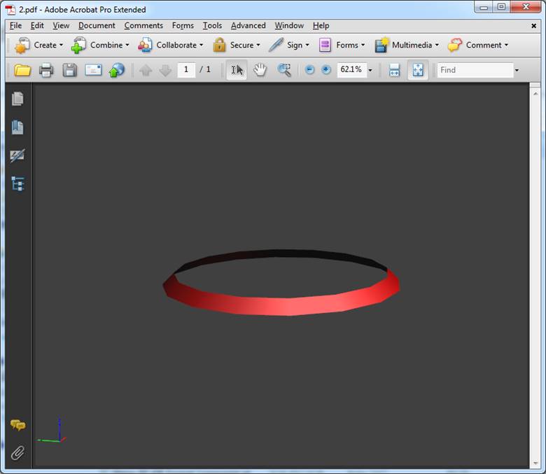
Created cone
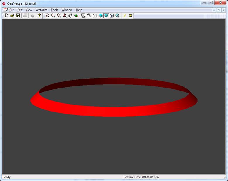
Created cone in OdaPrcApp