When we speak of 3D models in the mathematical sense, we usual refer to the “boundary representation” of solid bodies – their skin, as it were. Solids are so-called because their shape tends to be constant (cannot be easily modified), and their material is considered to be homogeneous throughout. By contrast, surface and mesh models are empty inside, but their skins can be modified in the extreme. In our industry, boundary representation is called “b-rep” for short.
I would like to briefly discuss boundary representation in the style of Abraham begat Isaac, Isaac begat Jacob. I’ll introduce b-rep concepts (without giving strict definitions) by providing illustrations. Detailed descriptions can be found in specialist literature.
The primary description of bodies is the boundary: the described object is the body bound, or shell, which separates space in two parts. One part, called inner, contains material and lays inside the body, and the other lays outside. The properties of shell are very similar to that of a surface. In practice, the boundaries of bodies are represented as sets of flat and curved faces.
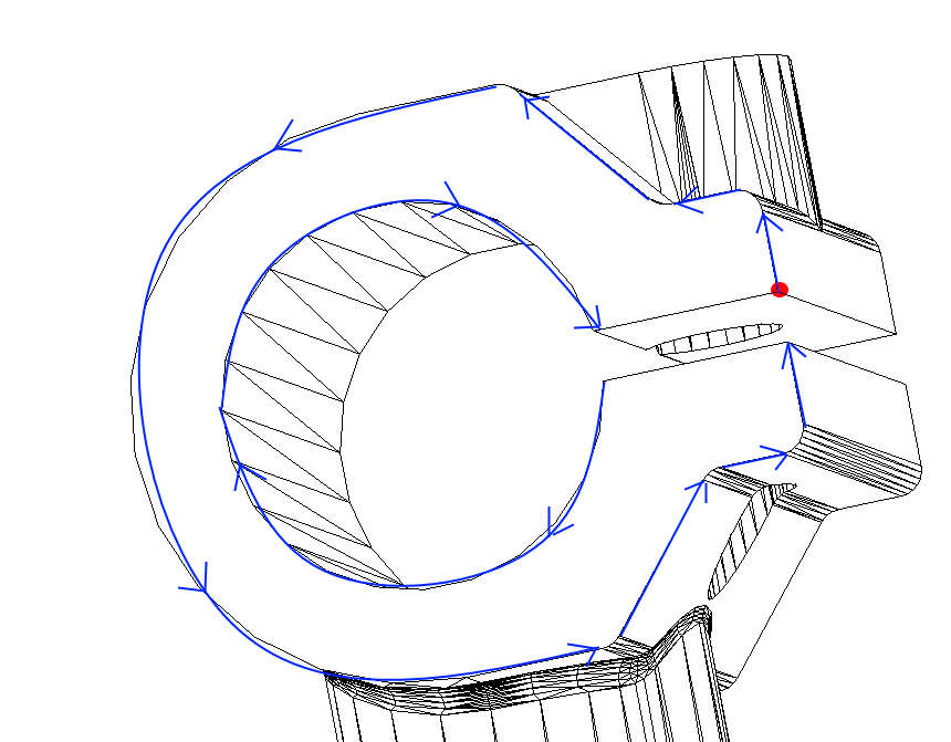
A face is a surface fragment that is oriented in a specific way and is linked to other faces in a defined way. The linking method works as follows: the boundary of each face is split into edges, and the transition from one face to the next is performed by at least one of the edges. On each face, the edges are grouped into closed, oriented chains called “loops.”
Edges are arranged in loops in such a way as to ensure the correct direction when passing the face: the face must be on the left hand side for the outer loop and on the right hand side for the inner loop. Each edge connects not only two faces, but also two vertices: the passage along the chain of oriented edges from one vertex to another also defines a loop: when we start from any vertex, we eventually return to it.
Shells, faces, loops, edges, and vertices (that is, the objects that describe the relative positions of geometry elements) are called “topological objects.”
Defining Geometry
You are unlikely to find a designer who manually describes the geometry of items, especially not the many relationships between faces and vertices. In fact, designers don’t even have to know anything about the functions that store models in CAD files, such as those used by the Open Design Alliance’s API to store three-dimensional data in the ModelSpace section of .dwg/.dxf files. As it turns out, 3D solids are stored as descriptions of b-rep Db3dSolid bodies in SAT format (short for “Save As Text”). This format was designed to facilitate exchange of data between the CAD system and the ACIS geometric kernel from Dassault Systemes Spatial.
Modern CAD systems provide designers with a rich set of tools based on a relatively small number of modeling operations. The correct combination of these operations allows designers to create items with complex shapes. Whether using a command-line interface or a graphical user interface, the UI transparently calls functions from the geometric kernel (also known simply as the “modeler”).
In the articles that follow, I will focus on this small set of operations that modelers provide to developers of CAD applications. Specifically, I will give an overview of some of the modeling operations provided by the ODA platform.