这是关于在 .dwg 文件中使用复合 DGN 线型系列文章中的第二篇。有关上一篇文章,请参阅第 1 部分。
创建线型修改器
DGN 线型的一个附加功能是能够修改其对选定实体的行为。如果我们需要对单个实体(或多个实体)的线型行为进行少量修改,我们不必创建单独的线型;我们可以改为将一个简单的线型修改器附加到此实体。
为了增强我们的复合线型演示,我们创建了一个额外的 OdDbCircle 实体:
// Create circle for LineStyle testing
OdDbCirclePtr pCircle = OdDbCircle::createObject();
pCircle->setDatabaseDefaults(pDb);
pCircle->setLinetype(lsId);
pCircle->setCenter(OdGePoint3d(1.15, -0.07, 0.0));
pCircle->setRadius(0.02);
OdDbBlockTableRecord::cast(pDb->getActiveLayoutBTRId().safeOpenObject(OdDb::kForWrite))->appendOdDbEntity(pCircle);
并使用以下简单代码为第二个线实体和创建的圆实体附加线型修改器:
// Set up LineStyle modifier for 2nd line and circle
OdGiDgLinetypeModifiers lsModifiers;
lsModifiers.setWidth(0.002); // Width override value
lsModifiers.setWidthFlag(true); // Enable width override
::oddbDgnLSWriteEntityXData(OdDbEntity::cast(lineIds[1].openObject(OdDb::kForWrite)), lsModifiers, 1.0);
::oddbDgnLSWriteEntityXData(pCircle, lsModifiers, 1.0);
OdGiDgLinetypeModifiers 结构提供了一组参数,这些参数可以在选定实体矢量化期间在现有线型中进行自定义。例如,我们使用 OdGiDgLinetypeModifiers::setWidth() 和 OdGiDgLinetypeModifiers::setWidthFlag() 方法启用了宽度覆盖。第一个设置宽度覆盖值,第二个用于启用此覆盖。请注意,单个宽度值表示线型虚线的恒定宽度,即对起始和结束虚线点使用相似的宽度值。要为起始和结束虚线点启用不同的宽度,可以使用 OdGiDgLinetypeModifiers::setEndWidth() 和 OdGiDgLinetypeModifiers::setEndWidthFlag() 方法。
此示例中的 ::oddbDgnLSWriteEntityXData() 函数用于将指定的修改器附加到选定实体。要调用它,请包含一个额外的头文件:
#include "DgnLS/DbLSXData.h"
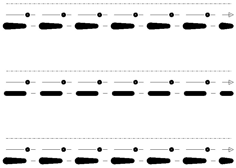
应用线型修改器后,中间线的复合线型行为有所不同:
仔细查看修改后的线型:
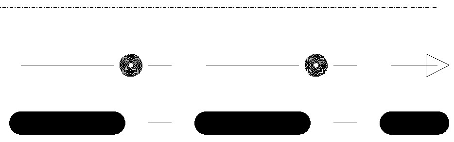
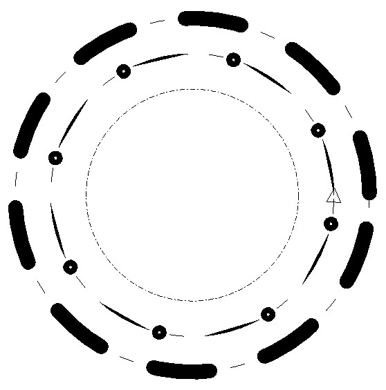
与原始复合线型的唯一区别是描边图案组件中虚线的宽度。这就是我们最终修改后的线型在圆形实体上的样子:
复合组件创建(完整命令源代码)
#include "DbLinetypeTable.h"
#include "DbLinetypeTableRecord.h"
#include "DbLine.h"
#include "DbCircle.h"
#include "Gi/GiDgLinetype.h"
#include "DgnLS/DbLSDefinition.h"
#include "DgnLS/DbLSCompoundComponent.h"
#include "DgnLS/DbLSXData.h"
#include "DgnLS/DbLSMisc.h"

// Declare commands from previous articles.
void _CreateDgnLineStyle_Stroke_func(OdEdCommandContext* pCmdCtx);
void _CreateDgnLineStyle_Internal_func(OdEdCommandContext* pCmdCtx);
void _CreateDgnLineStyle_Point_func(OdEdCommandContext* pCmdCtx);

void _CreateDgnLineStyle_Compound_func(OdEdCommandContext* pCmdCtx)
{
  OdDbDatabasePtr pDb = pCmdCtx->baseDatabase();
  OdDbUserIOPtr pIO = pCmdCtx->userIO();

  ::odrxDynamicLinker()->loadModule(OdDgnLSModuleName);

  // Create stroke, internal and point components
  _CreateDgnLineStyle_Stroke_func(pCmdCtx);
  _CreateDgnLineStyle_Internal_func(pCmdCtx);
  _CreateDgnLineStyle_Point_func(pCmdCtx);

  OdDbDictionaryPtr pLsDict = ::oddbDgnLSGetComponentsDictionary(pDb, OdDb::kForRead);
  OdDbObjectId strokeCompId = pLsDict->getAt(OD_T("DemoDgnLineStyleStrokeComponent"));
  OdDbObjectId internalCompId = pLsDict->getAt(OD_T("DemoDgnLineStyleInternalComponent"));
  OdDbObjectId pointCompId = pLsDict->getAt(OD_T("DemoDgnPointComponent"));
  OdDbObjectId pointStrokeCompId = pLsDict->getAt(OD_T("DemoDgnLineStyleStrokeComponentForPointComponent"));

  // We need GUID for DgnLS objects
  OdUInt8 dgnLS_UID[16];
  ::oddbDgnLSInitializeImportUID(dgnLS_UID);

  // Create Compound LineStyle Component
  OdDbLSCompoundComponentPtr pCompComponent = OdDbLSCompoundComponent::createObject();
  pCompComponent->setComponentType(kLSCompoundComponent);
  pCompComponent->setComponentUID(dgnLS_UID);

  // Append compound component sub-components
  pCompComponent->appendComponent(pointStrokeCompId);
  pCompComponent->appendComponent(pointCompId);
  pCompComponent->appendComponent(strokeCompId, -0.005);
  pCompComponent->appendComponent(internalCompId, 0.005);

  // Add component into LineStyles dictionary
  pLsDict->upgradeOpen();
  pLsDict->setAt(OD_T("DemoDgnLineStyleCompoundComponent"), pCompComponent);

  // Create LineStyle Definition
  OdDbLSDefinitionPtr pLSDef = OdDbLSDefinition::createObject();
  pLSDef->setComponent(pCompComponent->objectId());
  pLSDef->setComponentUID(pCompComponent->componentUID());

  // Create Linetype Table Record
  OdDbLinetypeTableRecordPtr pLtpRec = OdDbLinetypeTableRecord::createObject();
  pLtpRec->setName(OD_T("DemoDgnLineStyleCompound"));
  pLtpRec->setComments(OD_T("Compound component"));
  OdDbObjectId lsId = OdDbLinetypeTable::cast(pDb->getLinetypeTableId().safeOpenObject(OdDb::kForWrite))->add(pLtpRec);
  // Attach LineStyle Definition to Linetype Table Record
  pLtpRec->createExtensionDictionary();
  OdDbDictionaryPtr pLtpDict = OdDbDictionary::cast(pLtpRec->extensionDictionary().openObject(OdDb::kForWrite));
  pLtpDict->setAt(::oddbDgnLSGetDefinitionKeyName(), pLSDef);

  // Create three lines for LineStyle testing
  OdDbObjectId lineIds[3];
  for (int nLine = 0; nLine < 3; nLine++)
  {
    OdDbLinePtr pLine = OdDbLine::createObject();
    pLine->setDatabaseDefaults(pDb);
    pLine->setLinetype(lsId);
    pLine->setStartPoint(OdGePoint3d(1.1, 0.03 - 0.03 * nLine, 0.0));
    pLine->setEndPoint(OdGePoint3d(1.2, 0.03 - 0.03 * nLine, 0.0));
    lineIds[nLine] = OdDbBlockTableRecord::cast(pDb->getActiveLayoutBTRId().safeOpenObject(OdDb::kForWrite))->appendOdDbEntity(pLine);
  }

  // Create circle for LineStyle testing
  OdDbCirclePtr pCircle = OdDbCircle::createObject();
  pCircle->setDatabaseDefaults(pDb);
  pCircle->setLinetype(lsId);
  pCircle->setCenter(OdGePoint3d(1.15, -0.07, 0.0));
  pCircle->setRadius(0.02);
  OdDbBlockTableRecord::cast(pDb->getActiveLayoutBTRId().safeOpenObject(OdDb::kForWrite))->appendOdDbEntity(pCircle);

  // Set up LineStyle modifier for 2nd line and circle
  OdGiDgLinetypeModifiers lsModifiers;
  lsModifiers.setWidth(0.002); // Width override value
  lsModifiers.setWidthFlag(true); // Enable width override
  ::oddbDgnLSWriteEntityXData(OdDbEntity::cast(lineIds[1].openObject(OdDb::kForWrite)), lsModifiers, 1.0);
  ::oddbDgnLSWriteEntityXData(pCircle, lsModifiers, 1.0);
}
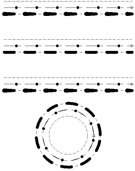
以下是命令执行生成的最终图片:
结论
在这些文章中,我们探讨了将 DGN 线型嵌入 .dwg 数据库的可能性。我们没有深入探讨每个线型功能的细节,但在阅读了这些介绍性主题后,您将能够独立地继续尝试 DGN 线型。
DGN 线型功能是一个强大的工具,它显著扩展了 .dwg 线型功能,可用于创建与 Autodesk® AutoCAD® 兼容的图纸。它使用简单,不需要关于内部矢量化过程的特殊知识,API 也很简单,因此在高级 CAD 编辑器中调用此功能应该没有限制。ODA Visualize SDK 调用相同的代码库来显示各种数据库的 DGN 线型,这保证了不同产品中线型行为的兼容性。DGN 线型矢量化代码库已成熟,并与 Bentley® MicroStation® 完全兼容。这是一个很好的例子,说明功能如何在不同产品和文件格式之间有效共享。