これは、Kernel SDK が平面クリッピング境界のカットジオメトリをどのようにサポートするかについての2部構成シリーズの最初の記事です。
クリッピングされたジオメトリとセクションジオメトリの生成に加えて、ODA SDK バージョン 20.3 以降、Kernel のクリッピングエンジンはカットジオメトリのジオメトリ出力を生成できます。
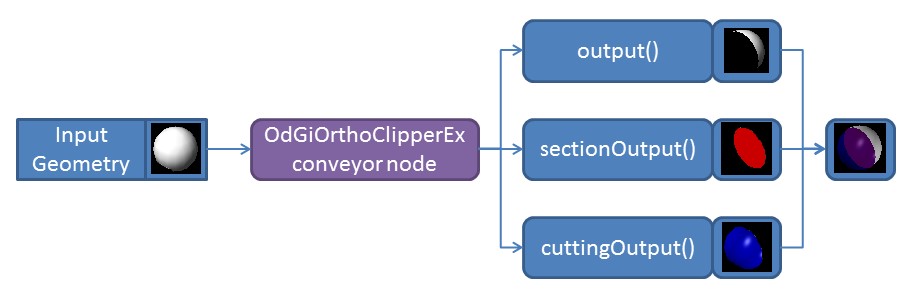
このジオメトリ出力構成はセクションジオメトリと非常によく似ており、一緒に使用できます。クライアントアプリケーションは、以前 ODA ブログで説明したセクションジオメトリと同様に、カットジオメトリの動作を制限なくカスタマイズできます。
断面化できないジオメトリのクリッピングを無効にする
デフォルトでは、断面化可能としてマークされていないすべてのジオメトリは、クリッピング平面によって単純にクリッピングされます。ODA SDK のクリッピングセクションインターフェースには、説明されている動作を無効にし、断面化できないジオメトリのクリッピングを回避するために使用できるフラグが含まれています。
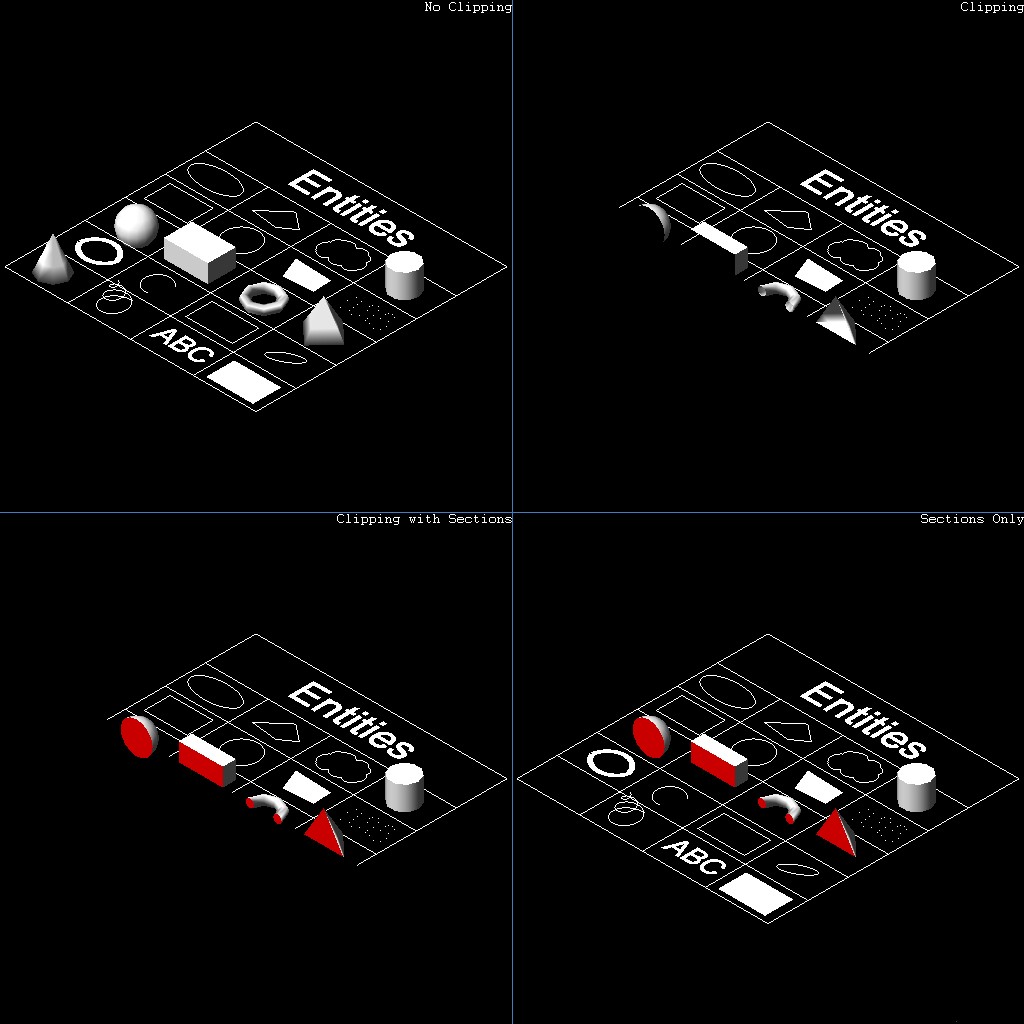
右下の図は、このフラグが使用されていることを示しています。左下の図は、断面化できないジオメトリのクリッピングが有効になっている標準的な動作を示しています。断面化できないジオメトリのクリッピングの動作は、OdGiSectionGeometryOutput::setNonSectionableGeometryClipping メソッドによって制御できます。
// Set up traits resolver for section geometry
OdGiSectionGeometryOutputPtr pTraitsSets = OdGiSectionGeometryOutput::createObject();
pTraitsSets->setTraitsOverrideFlags(OdGiSubEntityTraitsChangedFlags::kColorChanged | OdGiSubEntityTraitsChangedFlags::kMaterialChanged);
pTraitsSets->traitsOverrides().setColor(1);
pTraitsSets->setSectionToleranceOverride(1.0e-2);
pTraitsSets->setNonSectionableGeometryClipping(false);
// Set up clipping planes
OdGiPlanarClipBoundary::ClipPlaneArray clipPlanes;
clipPlanes.push_back(OdGiPlanarClipBoundary::ClipPlane(m_position, m_normal));
OdGiPlanarClipBoundary bnd; bnd.setClipPlanes(clipPlanes);
bnd.setSectionGeometryOutput(pTraitsSets);
カットジオメトリの生成とカスタマイズ
この例では、セクション生成に関する以前の記事の次のコードを使用します。
OdGiClipBoundary emptyBoundary; OdGiPlanarClipBoundary bnd;
::odgiEmptyClipBoundary(emptyBoundary);
// Set up traits resolver for section geometry
OdGiSectionGeometryOutputPtr pTraitsSets = OdGiSectionGeometryOutput::createObject();
pTraitsSets->setTraitsOverrideFlags(OdGiSubEntityTraitsChangedFlags::kColorChanged | OdGiSubEntityTraitsChangedFlags::kMaterialChanged);
pTraitsSets->traitsOverrides().setColor(1);
pTraitsSets->setSectionToleranceOverride(1.0e-2);
// Set up clipping planes
OdGiPlanarClipBoundary::ClipPlaneArray clipPlanes;
clipPlanes.push_back(OdGiPlanarClipBoundary::ClipPlane(OdGePoint3d(202.875, 343.1696, 0.0),
                                                         OdGeVector3d(563.1322 - 247.9639, 172.293 - 147.2914, 0.0)));
clipPlanes.push_back(OdGiPlanarClipBoundary::ClipPlane(OdGePoint3d(247.9639, 147.2914, 0.0),
                                                         OdGeVector3d(202.875 - 247.9639, 343.1696 - 147.2914, 0.0)));
// Set up planar boundary
bnd.setClipPlanes(clipPlanes);
bnd.setSectionGeometryOutput(pTraitsSets);
// Set up viewport clipping
pGsView->setViewport3dClipping(&emptyBoundary, &bnd);
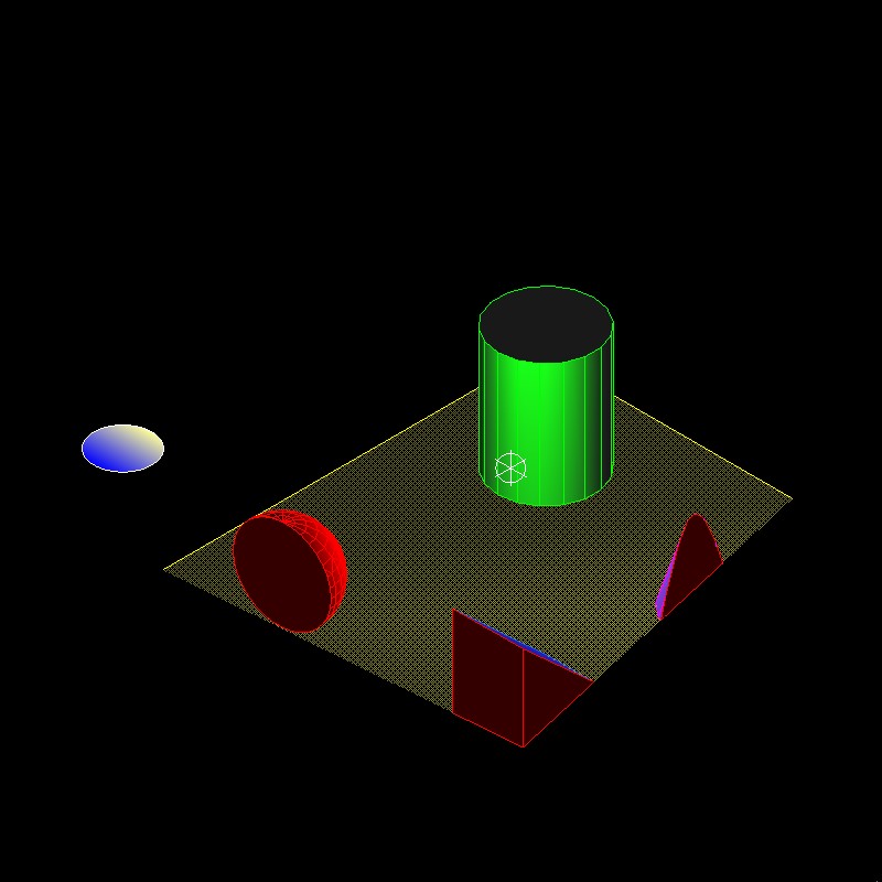
このコードは、OdGsView (pGsView) オブジェクトに2つのクリッピング平面を適用し、セクションジオメトリの出力を有効にします。セクションジオメトリ出力は、赤色を使用してジオメトリを出力するようにカスタマイズされています。このコードを使用すると、次の画像をベクトル化できます。
これで、上記のコードをカスタマイズして、セクションの代わりにカットジオメトリを生成できます。
OdGiClipBoundary emptyBoundary; OdGiPlanarClipBoundary bnd;
::odgiEmptyClipBoundary(emptyBoundary);
// Set up traits resolver for cutted geometry
OdGiCuttedGeometryOutputPtr pTraitsSets = OdGiCuttedGeometryOutput::createObject();
pTraitsSets->setTraitsOverrideFlags(OdGiSubEntityTraitsChangedFlags::kColorChanged | OdGiSubEntityTraitsChangedFlags::kMaterialChanged);
pTraitsSets->traitsOverrides().setColor(5);
// Set up clipping planes
OdGiPlanarClipBoundary::ClipPlaneArray clipPlanes;
clipPlanes.push_back(OdGiPlanarClipBoundary::ClipPlane(OdGePoint3d(202.875, 343.1696, 0.0),
                                                         OdGeVector3d(563.1322 - 247.9639, 172.293 - 147.2914, 0.0)));
clipPlanes.push_back(OdGiPlanarClipBoundary::ClipPlane(OdGePoint3d(247.9639, 147.2914, 0.0),
                                                         OdGeVector3d(202.875 - 247.9639, 343.1696 - 147.2914, 0.0)));
// Set up planar boundary
bnd.setClipPlanes(clipPlanes);
bnd.setCuttedGeometryOutput(pTraitsSets);
// Set up viewport clipping
pGsView->setViewport3dClipping(&emptyBoundary, &bnd);
コードの違いは最小限です。
- OdGiSectionGeometryOutput クラスの代わりに OdGiCuttedGeometryOutput クラスが使用されます。
- カットジオメトリ出力インターフェースを設定するために、OdGiPlanarClipBoundary::setSectionGeometryOutput メソッドの代わりに OdGiPlanarClipBoundary::setCuttedGeometryOutput メソッドが使用されます。
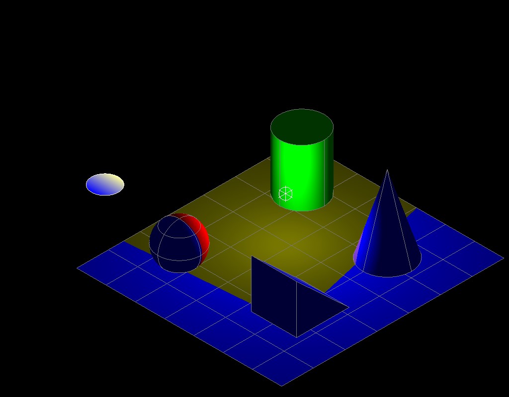
セクションジオメトリと同様に、カットジオメトリ出力インターフェースには、非セクション可能ジオメトリクリッピングの動作を制御するための OdGiCuttedGeometryOutput::setNonSectionableGeometryClipping メソッドが含まれています。 このシリーズの次の記事については、ODAブログをご覧ください。