[ブログに戻る](/ja/blog) # .dwgファイルで複合.dgn線種を使用する (パート2/2)
Andrew Markovich 4月 26, 2019 [\#.dwg](/ja/blog/tag/dwg) [\#dgn](/ja/blog/tag/dgn) [\#Example](/ja/blog/tag/example)
これは、.dwgファイルで複合DGN線種を使用することに関するシリーズの2番目の記事です。前の記事については、[パート1](https://www.opendesign.com/blog/2019/april/using-compound-dgn-line-styles-dwg-file-part-1-2)を参照してください。
#### 線種修飾子の作成
DGN線種の追加機能は、選択したエンティティの動作を変更できることです。単一のエンティティ (または複数のエンティティ) の線種動作に小さな変更が必要な場合、個別の線種を作成する必要はありません。代わりに、このエンティティに単純な線種修飾子をアタッチできます。
複合線種のデモンストレーションを強化するために、追加のOdDbCircleエンティティを作成します:
```
// Create circle for LineStyle testing
OdDbCirclePtr pCircle = OdDbCircle::createObject();
pCircle->setDatabaseDefaults(pDb);
pCircle->setLinetype(lsId);
pCircle->setCenter(OdGePoint3d(1.15, -0.07, 0.0));
pCircle->setRadius(0.02);
OdDbBlockTableRecord::cast(pDb->getActiveLayoutBTRId().safeOpenObject(OdDb::kForWrite))->appendOdDbEntity(pCircle);
```
そして、以下のシンプルなコードを使用して、2番目の線エンティティと作成された円エンティティに線種修飾子をアタッチします:
```
// Set up LineStyle modifier for 2nd line and circle
OdGiDgLinetypeModifiers lsModifiers;
lsModifiers.setWidth(0.002); // Width override value
lsModifiers.setWidthFlag(true); // Enable width override
::oddbDgnLSWriteEntityXData(OdDbEntity::cast(lineIds[1].openObject(OdDb::kForWrite)), lsModifiers, 1.0);
::oddbDgnLSWriteEntityXData(pCircle, lsModifiers, 1.0);
```
OdGiDgLinetypeModifiers構造体は、選択されたエンティティのベクトル化中に既存の線種でカスタマイズできる一連のパラメーターを提供します。ここでは、例えば、OdGiDgLinetypeModifiers::setWidth()およびOdGiDgLinetypeModifiers::setWidthFlag()メソッドを使用して幅のオーバーライドを有効にしました。最初のメソッドは幅のオーバーライド値を設定し、2番目のメソッドはこのオーバーライドを有効にするために使用されます。単一の幅の値は、線種の破線に対して一定の幅を意味すること、つまり、開始点と終了点の破線に同様の幅の値を使用することに注意してください。開始点と終了点の破線に異なる幅を有効にするには、OdGiDgLinetypeModifiers::setEndWidth()およびOdGiDgLinetypeModifiers::setEndWidthFlag()メソッドを使用できます。
この例の::oddbDgnLSWriteEntityXData()関数は、指定された修飾子を選択されたエンティティにアタッチするために使用されます。これを呼び出すには、追加のヘッダーファイルを含めます:
```
#include "DgnLS/DbLSXData.h"
```
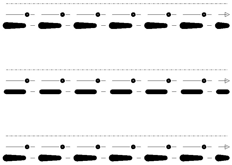
線種修飾子を適用すると、中央の線に対して異なる複合線種動作が得られます:
変更された線種をよく見てください:
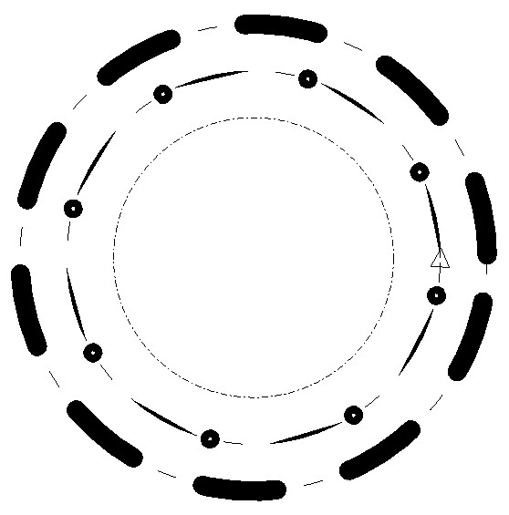
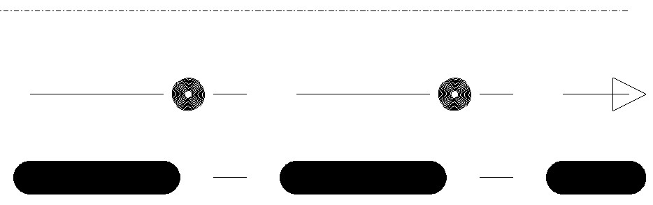元の複合線種スタイルとの唯一の違いは、ストロークパターンコンポーネントのダッシュの幅です。そして、これが最終的に修正された線種スタイルが円エンティティ上でどのように見えるかです。
#### 複合コンポーネントの作成(完全なコマンドソースコード)
```
#include "DbLinetypeTable.h"
#include "DbLinetypeTableRecord.h"
#include "DbLine.h"
#include "DbCircle.h"
#include "Gi/GiDgLinetype.h"
#include "DgnLS/DbLSDefinition.h"
#include "DgnLS/DbLSCompoundComponent.h"
#include "DgnLS/DbLSXData.h"
#include "DgnLS/DbLSMisc.h"
// Declare commands from previous articles.
void _CreateDgnLineStyle_Stroke_func(OdEdCommandContext* pCmdCtx);
void _CreateDgnLineStyle_Internal_func(OdEdCommandContext* pCmdCtx);
void _CreateDgnLineStyle_Point_func(OdEdCommandContext* pCmdCtx);
void _CreateDgnLineStyle_Compound_func(OdEdCommandContext* pCmdCtx)
{
OdDbDatabasePtr pDb = pCmdCtx->baseDatabase();
OdDbUserIOPtr pIO = pCmdCtx->userIO();
::odrxDynamicLinker()->loadModule(OdDgnLSModuleName);
// Create stroke, internal and point components
_CreateDgnLineStyle_Stroke_func(pCmdCtx);
_CreateDgnLineStyle_Internal_func(pCmdCtx);
_CreateDgnLineStyle_Point_func(pCmdCtx);
OdDbDictionaryPtr pLsDict = ::oddbDgnLSGetComponentsDictionary(pDb, OdDb::kForRead);
OdDbObjectId strokeCompId = pLsDict->getAt(OD_T("DemoDgnLineStyleStrokeComponent"));
OdDbObjectId internalCompId = pLsDict->getAt(OD_T("DemoDgnLineStyleInternalComponent"));
OdDbObjectId pointCompId = pLsDict->getAt(OD_T("DemoDgnPointComponent"));
OdDbObjectId pointStrokeCompId = pLsDict->getAt(OD_T("DemoDgnLineStyleStrokeComponentForPointComponent"));
// We need GUID for DgnLS objects
OdUInt8 dgnLS_UID[16];
::oddbDgnLSInitializeImportUID(dgnLS_UID);
// Create Compound LineStyle Component
OdDbLSCompoundComponentPtr pCompComponent = OdDbLSCompoundComponent::createObject();
pCompComponent->setComponentType(kLSCompoundComponent);
pCompComponent->setComponentUID(dgnLS_UID);
// Append compound component sub-components
pCompComponent->appendComponent(pointStrokeCompId);
pCompComponent->appendComponent(pointCompId);
pCompComponent->appendComponent(strokeCompId, -0.005);
pCompComponent->appendComponent(internalCompId, 0.005);
// Add component into LineStyles dictionary
pLsDict->upgradeOpen();
pLsDict->setAt(OD_T("DemoDgnLineStyleCompoundComponent"), pCompComponent);
// Create LineStyle Definition
OdDbLSDefinitionPtr pLSDef = OdDbLSDefinition::createObject();
pLSDef->setComponent(pCompComponent->objectId());
pLSDef->setComponentUID(pCompComponent->componentUID());
// Create Linetype Table Record
OdDbLinetypeTableRecordPtr pLtpRec = OdDbLinetypeTableRecord::createObject();
pLtpRec->setName(OD_T("DemoDgnLineStyleCompound"));
pLtpRec->setComments(OD_T("Compound component"));
OdDbObjectId lsId = OdDbLinetypeTable::cast(pDb->getLinetypeTableId().safeOpenObject(OdDb::kForWrite))->add(pLtpRec);
// Attach LineStyle Definition to Linetype Table Record
pLtpRec->createExtensionDictionary();
OdDbDictionaryPtr pLtpDict = OdDbDictionary::cast(pLtpRec->extensionDictionary().openObject(OdDb::kForWrite));
pLtpDict->setAt(::oddbDgnLSGetDefinitionKeyName(), pLSDef);
// Create three lines for LineStyle testing
OdDbObjectId lineIds[3];
for (int nLine = 0; nLine < 3; nLine++)
{
OdDbLinePtr pLine = OdDbLine::createObject();
pLine->setDatabaseDefaults(pDb);
pLine->setLinetype(lsId);
pLine->setStartPoint(OdGePoint3d(1.1, 0.03 - 0.03 * nLine, 0.0));
pLine->setEndPoint(OdGePoint3d(1.2, 0.03 - 0.03 * nLine, 0.0));
lineIds[nLine] = OdDbBlockTableRecord::cast(pDb->getActiveLayoutBTRId().safeOpenObject(OdDb::kForWrite))->appendOdDbEntity(pLine);
}
// Create circle for LineStyle testing
OdDbCirclePtr pCircle = OdDbCircle::createObject();
pCircle->setDatabaseDefaults(pDb);
pCircle->setLinetype(lsId);
pCircle->setCenter(OdGePoint3d(1.15, -0.07, 0.0));
pCircle->setRadius(0.02);
OdDbBlockTableRecord::cast(pDb->getActiveLayoutBTRId().safeOpenObject(OdDb::kForWrite))->appendOdDbEntity(pCircle);
// Set up LineStyle modifier for 2nd line and circle
OdGiDgLinetypeModifiers lsModifiers;
lsModifiers.setWidth(0.002); // Width override value
lsModifiers.setWidthFlag(true); // Enable width override
::oddbDgnLSWriteEntityXData(OdDbEntity::cast(lineIds[1].openObject(OdDb::kForWrite)), lsModifiers, 1.0);
::oddbDgnLSWriteEntityXData(pCircle, lsModifiers, 1.0);
}
```
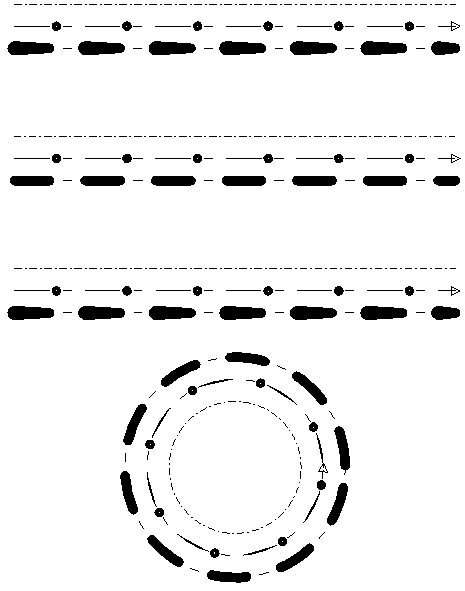
コマンド実行によって生成される最終的な画像は次のとおりです。
#### 結論
これらの記事では、DGN線種スタイルを.dwgデータベースに埋め込みながら、その可能性を検討しました。各線種スタイルの機能の詳細には触れませんでしたが、これらの入門的なトピックを読んだ後、DGN線種スタイルを独自に試すことができるようになるでしょう。
DGN線種スタイル機能は、.dwg線種機能を大幅に拡張し、Autodesk® AutoCAD®互換の図面を作成するために使用できる強力なツールです。使い方は簡単で、内部のベクトル化プロセスに関する特別な知識は必要ありません。APIはシンプルであるため、高度なCADエディタでこの機能を呼び出すことに制限はありません。ODA Visualize SDKは、あらゆる種類のデータベースでDGN線種スタイルを表示するために同じコードベースを呼び出すため、これにより異なる製品間での線種動作の互換性が保証されます。DGN線種スタイルのベクトル化コードベースは十分に確立されており、Bentley® MicroStation®と完全に互換性があります。これは、機能が異なる製品やファイル形式間でいかに効果的に共有できるかを示す良い例です。
## 今すぐ始める
**ODAソフトウェアを60日間無料でお試しください。
リスクなし、クレジットカード不要。**
[無料で試す](https://www.opendesign.com/ja/free-trial)