[返回博客](/cn/blog) # ODA Mechanical SDK: 使用符号引线
Dmytro Kabenok 十二月 17, 2021 [\#mechanical](/cn/blog/tag/mechanical) [\#getting started](/cn/blog/tag/getting-started)
#### 概述
AcmCLeaderNodeIterator 提供了与引线内部结构交互的功能。每个引线可以包含许多节点(或不包含节点)。这些节点相互连接,形成树状结构。在大多数情况下,节点之间的连接很简单,看起来像是一系列点,沿着这些点依次绘制线条。但也可能存在复杂情况,即每个主点都有分支,这些分支可能看起来像带有叶子的树枝。创建 AcmCLeaderNodeIterator 的目的是无论树的复杂程度如何,都能单独与每个节点进行交互。该迭代器允许您添加新节点、删除当前节点、搜索父分支、获取节点的坐标、查找分支数量等等。
#### 创建引线
要使用 AcmCLeaderNodeIterator 功能,请包含以下文件:
```
#include "AcmCLeaderNodeIterator.h"
```
要从机械符号获取迭代器,您还需要包含以下文件:
```
#include "AcmCLeader.h"
#include "AcmSurfaceTexture.h" // In your case it can be any other mechanical symbol
```
以下是从机械符号 AcmSurfaceTexture 创建和获取迭代器的示例代码(其他机械符号的代码类似)。
**注意:**PartList、PartRef、HoleChart 和 SectionSym 对象不支持引线。
```
OdDbDatabasePtr pDb = ... // get database
// Create and initialize symbol data. If something is wrong, such as a symbol or
// symbol standard is not supported by the current standard, a code other than
// Acm::eOk will be returned.
AcmSurfaceTexturePtr pSymb = AcmSurfaceTexture::createObject();
if (pSymb->setSymbolDefaults(pDb) != Acm::eOk)
return;
// Add points to array and call the addLeader() method for leader creation
OdGePoint3dArray points;
points.setLogicalLength(3);
points[0].set(10.0, 30.0, 0.0);
points[1].set(50.0, 60.0, 0.0);
points[2].set(70.0, 65.0, 0.0);
// Acm::eOk will be returned if the leader for the symbol was successfully created
if (pSymb->addLeader(points) != Acm::eOk)
return;
// Get leader. Since we have added only one leader, its index will be 0
AcmCLeader* pLeader = pSymb->getLeader(0);
if (!pLeader)
return;
// Get leader iterator
AcmCLeaderNodeIteratorPtr pIt = pLeader->newNodeIterator();
if (pIt.isNull())
return;
// Next step is iterator data initialization.
// This method will collect all nodes or only leafs of tree structure depending
// on how the input flag is set. By default, it collects all nodes.
pIt->start(false);
// To make sure that the iterator has been initialized correctly and the leader
// contains at least one node, call the done() iterator method. In the future,
// this method can be used to check if all nodes have been walked through.
if (pIt->done())
return;
// Get and open ModelSpace blockRecord
OdDbBlockTableRecordPtr pMSpace =
OdDbBlockTableRecord::cast(pDb->getModelSpaceId().openObject(OdDb::kForWrite));
if (pMSpace.isNull())
return;
// Now we can add AcmSurfaceTexture to the ModelSpace in order to look at the
// result of entity creation
pMSpace->appendOdDbEntity(pSymb);
```
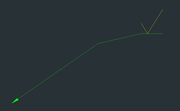
结果,创建了一个简单的 AcmSurfaceTexture 实体:
#### 修改引线
要移动到下一个节点,请使用迭代器方法 step()。如果迭代器有前一个节点,此方法也允许您后退。要后退一个节点,请将 step() 方法的传入参数设置为 true。
如果您需要获取当前节点的坐标,请调用 vertex() 方法。如果您想为当前节点设置新位置,请使用 setVertex() 方法。
**注意:**节点的计数是按照与符号的距离的逻辑顺序开始的,而不是按照从 AcmSymbol 派生类调用 addLeader() 方法时点添加到数组的顺序。下面是顶点编号(也视为节点)和顶点坐标的图片。
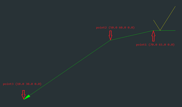要移动到不同的节点并更改第二个节点的坐标,请参阅以下代码,该代码还获取所有节点的坐标并找出当前节点有多少个分支。
```
// Get the number of branches spun off from the current node
int branchesOfNode1 = pIt->numOfBranches(); // result: 1
// Get node coordinates
OdGePoint3d point1 = pIt->vertex(); // result: 70.0 65.0 0.0
// Step to the next node
pIt->step();
int branchesOfNode2 = pIt->numOfBranches(); // result: 1
OdGePoint3d point2 = pIt->vertex(); // result: 50.0 60.0 0.0
pIt->step();
int branchesOfNode3 = pIt->numOfBranches(); // result: 0 (because it's the last node)
OdGePoint3d point3 = pIt->vertex(); // result: 10.0 30.0 0.0
// Step backward and change vertex of second node
pIt->step(true);
pIt->setVertex(OdGePoint3d(40.0, 40.0, 0.0));
point2 = pIt->vertex(); // result: 40.0 40.0 0.0 (coordinates were updated)
```
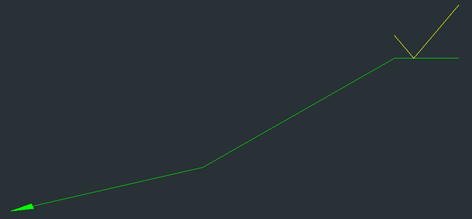
经过这些操作后,符号引线如下所示:
#### 使用引线段
要创建与当前节点关联的新引线段(节点集),请使用迭代器方法 addLeader()。
**注意:**添加新段后,迭代器不会移动到最后添加的节点,而是停留在当前位置。添加新段后,从当前节点发出的分支数量会增加。这可以通过 numOfBranches() 方法进行检查。
```
// Add a new leader segment based on points from input array
OdGePoint3dArray pointsForNewNodes;
pointsForNewNodes.setLogicalLength(2);
pointsForNewNodes[0].set(25.0, 45.0, 0.0);
pointsForNewNodes[1].set(15.0, 45.0, 0.0);
pIt->addLeader(pointsForNewNodes);
// Get coordinates for the current node
OdGePoint3d currentVertex = pIt->vertex(); // result: 40.0 40.0 0.0
// Count of branches will increase after adding a new segment
int branchesCount = pIt->numOfBranches(); // result: 2
```
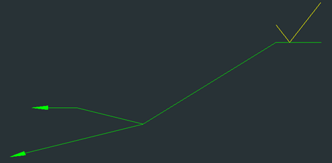
添加新段后,符号引线如下所示:
要创建用于迭代连接到此节点的引线段的新引线迭代器,请使用 newNodeIterator() 方法。作为输入参数,指定要遍历的段的索引。选择一个新创建的段作为示例;其索引为 1。这是因为新分支被添加到数组的末尾,并且之前数组中已经有一个分支。
您还可以使用 isLeafNode() 方法来判断此节点是否是最后一个节点和叶节点。此方法不仅可以从新段的迭代器调用,也可以从主迭代器调用。
```
// Create a new iterator for the new leader segment
AcmCLeaderNodeIteratorPtr pNewSegIt = pIt->newNodeIterator(1);
if (pNewSegIt.isNull())
return;
// Initialize the new iterator and check if it contains data or not
pNewSegIt->start();
if (pNewSegIt->done())
return;
// Check if the current node is a leaf
bool isLeaf = pNewSegIt->isLeafNode(); // result: false
```
您可以移动到下一个节点并检查它是否是叶节点。您还可以使用 transformBy() 方法更改顶点的坐标。
```
pNewSegIt->step();
isLeaf = pNewSegIt->isLeafNode(); // result: true
OdGeMatrix3d mtrx;
mtrx.setToScaling(1.2);
pNewSegIt->transformBy(mtrx);
```
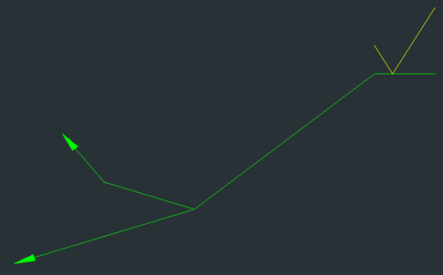
经过这些操作后,符号引线如下所示:
#### 使用节点
要将迭代器返回到上一个节点,除了 step() 方法之外,您还可以使用 parent() 方法。parent() 方法更具相关性,因为如果您仅使用叶元素初始化迭代器,则后退一步会将迭代器设置为迭代器节点数组中的上一个节点,而不是父元素(父元素可能根本不在数组中)。如果迭代器成功移动到父节点,则返回 true 作为结果。
```
// Set iterator to the parent node
pNewSegIt->parent(); // result: true
```
##### 添加节点
要在当前节点之前添加新节点,请使用 insertBefore() 方法。作为输入参数,传入创建新节点的坐标点。如果当前节点没有父节点或迭代器未初始化,则返回 Acm::eBad 作为结果。
```
// Insert a new node in front of the node that the iterator is currently pointing at
Acm::ErrorStatus es = pNewSegIt->insertBefore(OdGePoint3d(32.0, 48.0, 0.0)); // result: Acm::eOk
```
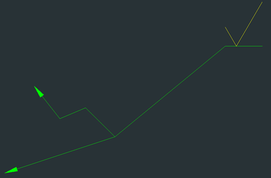
插入新节点后,符号引线如下所示:
##### 删除节点
要删除其中一个节点,请使用 remove() 方法。例如,假设当前节点被命名为迭代器指向的节点。因此,remove() 方法将当前节点之后的下一个节点与当前节点之前的节点合并,并删除当前节点。它看起来就像当前节点被从链中移除,但链不会断裂并会重建。
```
// Remove the node to which the iterator is pointing now
pNewSegIt->remove();
```
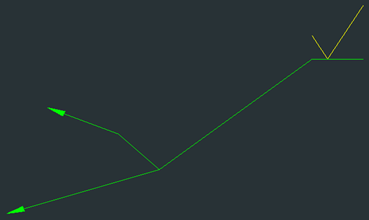
删除其中一个节点后,引线符号如下所示:
除了只删除一个节点外,您还可以调用 trim() 方法来完全剪断所有分支,包括迭代器指向的当前节点。在这种情况下,迭代器会移动到上一个节点,所有其他节点都会消失。此方法执行的操作与 removeLeader() 方法相同。
对迭代器执行多项操作后,通过再次初始化主迭代器来更新其中的数据,以便您可以到达所需的节点。为了使删除更直观,请先添加一个节点,然后调用 trim() 方法。
```
// Update data in the iterator after calls of different methods
pIt->start(); // set the iterator to the first node
pIt->step(); // move the iterator pointer to the second node where forking is present
pIt->insertBefore(OdGePoint3d(60.0, 62.5, 0.0)); // insert a new node
pIt->trim(); // cut off all next leader segments starting from the current
```
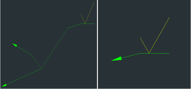
下图显示了添加新节点后(左)和修剪后(右)的引线外观:
##### 查找节点
要查找引线节点,请使用以下三种迭代器方法之一:
- virtual Acm::ErrorStatus find(const OdGePoint3d& pt, bool fromTipPoint = true) = 0;
根据给定点进行搜索,并可指定从何处开始搜索。如果将 fromTipPoint 指定为 true(默认值),则搜索从第一个节点开始执行,无论迭代器当前指向何处。如果将 fromTipPoint 指定为 false,则搜索从当前节点开始,在迭代器数组中剩余的节点上进行。
- virtual Acm::ErrorStatus findClosest(const OdGePoint3d& pt) = 0;
搜索最近的点。搜索在依赖于当前节点的节点中执行。如果找到一个点,迭代器指针将指向它。
- virtual Acm::ErrorStatus findByGrip(int indice) = 0;
使用其夹点索引查找节点,并将迭代器指针设置为找到的节点。
对于所有这三种方法,如果失败,将返回与 Acm::eOk 不同的结果。
##### 处理节点几何
AcmCLeaderNodeIterator 具有以下用于处理几何的方法:
- virtual Acm::ErrorStatus attachGeomRef(const void\* pGeometry, const OdDbObjectId& viewId, OdGePoint3d& prevLocation, bool hasReactor = false) = 0;
将几何图形附加到节点。此方法需要与 AcmSymbol 类继承者的 attachGeomRef() 方法相同的方法(有关详细信息,请参阅位于 /Mechanical/Examples 目录中的 Mechanical 示例,其中 <INSTALL\_DIR> 是您解压 Mechanical SDK 存档的目录)。
- virtual Acm::ErrorStatus detachGeomRef() = 0;
如果存在几何图形,则从当前节点分离几何图形。
- virtual void releaseGeomRef() = 0;
执行几何图形的释放。
##### 获取附件状态
还有三种方法用于获取当前附件的状态信息:
- virtual OdDbObjectId viewId() const = 0;
获取节点关联的视图ID。
- virtual bool isAttachedNoView() const = 0;
检查节点是否未连接到视图。
- virtual bool isAttachedToView(OdDbObjectId& viewId) const = 0;
检查节点是否已连接到视图。
## 今天就开始行动
**免费试用 ODA 软件 60 天。
无风险,无需信用卡。**
[免费试用](https://www.opendesign.com/cn/free-trial)