[返回博客](/cn/blog) # 第 1 部分,共 2 部分:为平面裁剪边界生成切割几何体
Andrew Markovich 八月 22, 2019 [\#geometry](/cn/blog/tag/geometry) [\#cutting planes](/cn/blog/tag/cutting-planes)
这是关于 Kernel SDK 如何支持平面裁剪边界的切割几何体的两部分系列文章中的第一篇。
除了生成裁剪和截面几何体之外,从 ODA SDK 20.3 版本开始,Kernel 中的裁剪引擎可以为切割几何体生成几何体输出:
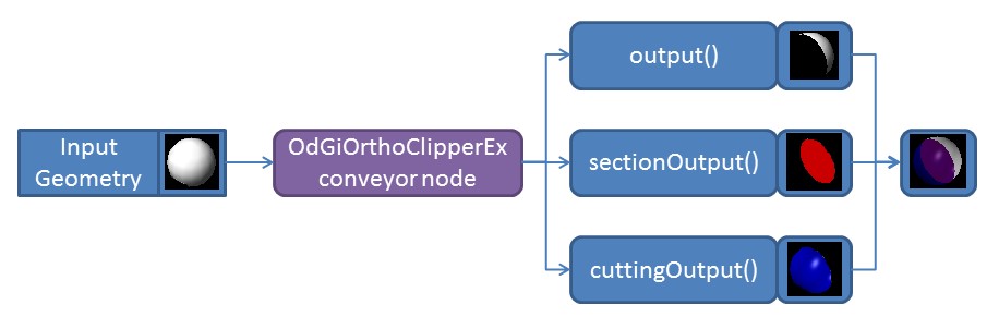此几何体输出配置与截面几何体非常相似,可以与截面几何体一起使用。客户端应用程序可以无限制地自定义切割几何体的行为,类似于之前在 ODA 博客上描述的截面几何体。
#### 禁用不可截面几何体裁剪
默认情况下,所有未标记为可截面的几何体都会被裁剪平面简单地裁剪。ODA SDK 的裁剪截面接口包含一个标志,可用于禁用所述行为并避免裁剪不可截面几何体。
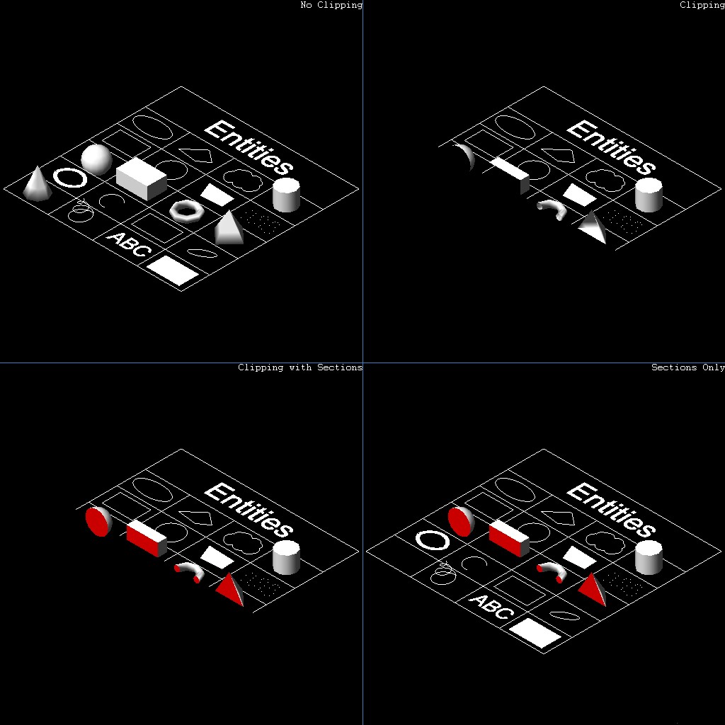右下角的插图显示了此标志的使用。左下角显示了启用不可截面几何体裁剪的标准行为。不可截面几何体裁剪的行为可以通过 OdGiSectionGeometryOutput::setNonSectionableGeometryClipping 方法控制:
```
// Set up traits resolver for section geometry
OdGiSectionGeometryOutputPtr pTraitsSets = OdGiSectionGeometryOutput::createObject();
pTraitsSets->setTraitsOverrideFlags(OdGiSubEntityTraitsChangedFlags::kColorChanged | OdGiSubEntityTraitsChangedFlags::kMaterialChanged);
pTraitsSets->traitsOverrides().setColor(1);
pTraitsSets->setSectionToleranceOverride(1.0e-2);
pTraitsSets->setNonSectionableGeometryClipping(false);
// Set up clipping planes
OdGiPlanarClipBoundary::ClipPlaneArray clipPlanes;
clipPlanes.push_back(OdGiPlanarClipBoundary::ClipPlane(m_position, m_normal));
OdGiPlanarClipBoundary bnd; bnd.setClipPlanes(clipPlanes);
bnd.setSectionGeometryOutput(pTraitsSets);
```
#### 生成和自定义切割几何体
对于此示例,我们将使用上一篇关于截面生成的文章中的以下代码:
```
OdGiClipBoundary emptyBoundary; OdGiPlanarClipBoundary bnd;
::odgiEmptyClipBoundary(emptyBoundary);
// Set up traits resolver for section geometry
OdGiSectionGeometryOutputPtr pTraitsSets = OdGiSectionGeometryOutput::createObject();
pTraitsSets->setTraitsOverrideFlags(OdGiSubEntityTraitsChangedFlags::kColorChanged | OdGiSubEntityTraitsChangedFlags::kMaterialChanged);
pTraitsSets->traitsOverrides().setColor(1);
pTraitsSets->setSectionToleranceOverride(1.0e-2);
// Set up clipping planes
OdGiPlanarClipBoundary::ClipPlaneArray clipPlanes;
clipPlanes.push_back(OdGiPlanarClipBoundary::ClipPlane(OdGePoint3d(202.875, 343.1696, 0.0),
OdGeVector3d(563.1322 - 247.9639, 172.293 - 147.2914, 0.0)));
clipPlanes.push_back(OdGiPlanarClipBoundary::ClipPlane(OdGePoint3d(247.9639, 147.2914, 0.0),
OdGeVector3d(202.875 - 247.9639, 343.1696 - 147.2914, 0.0)));
// Set up planar boundary
bnd.setClipPlanes(clipPlanes);
bnd.setSectionGeometryOutput(pTraitsSets);
// Set up viewport clipping
pGsView->setViewport3dClipping(&emptyBoundary, &bnd);
```
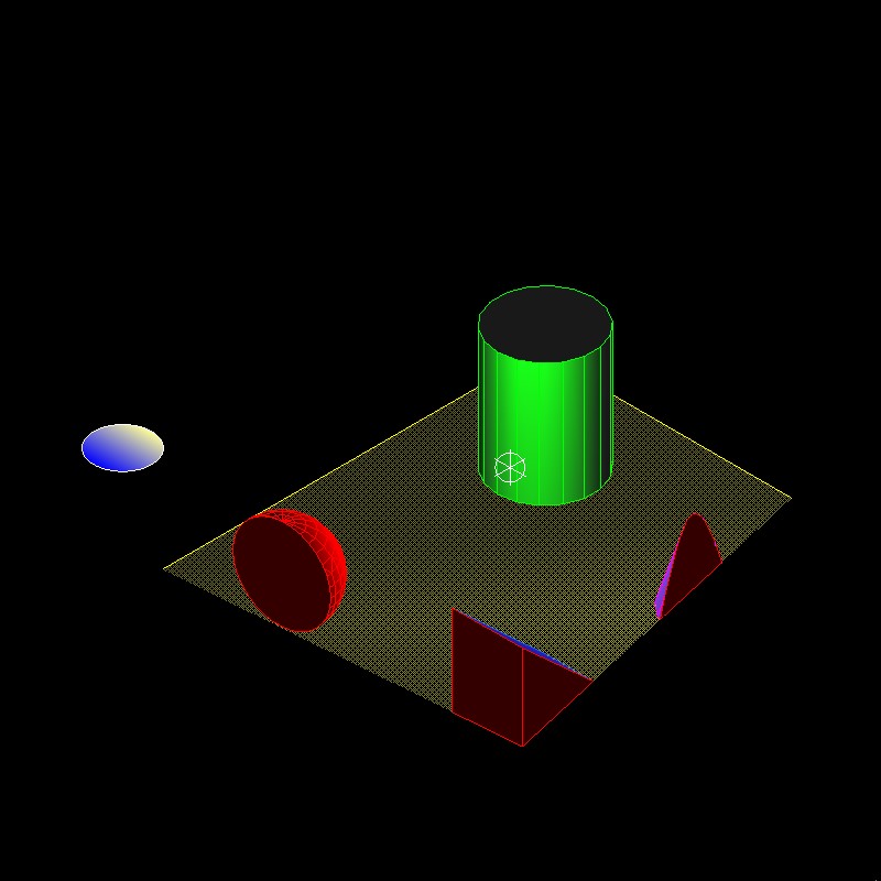
此代码将两个裁剪平面应用于 OdGsView (pGsView) 对象,并启用截面几何体的输出。截面几何体输出被自定义为使用红色输出几何体。使用此代码,我们可以矢量化以下图像:
现在我们可以自定义上述代码以生成切割几何体而不是截面:
```
OdGiClipBoundary emptyBoundary; OdGiPlanarClipBoundary bnd;
::odgiEmptyClipBoundary(emptyBoundary);
// Set up traits resolver for cutted geometry
OdGiCuttedGeometryOutputPtr pTraitsSets = OdGiCuttedGeometryOutput::createObject();
pTraitsSets->setTraitsOverrideFlags(OdGiSubEntityTraitsChangedFlags::kColorChanged | OdGiSubEntityTraitsChangedFlags::kMaterialChanged);
pTraitsSets->traitsOverrides().setColor(5);
// Set up clipping planes
OdGiPlanarClipBoundary::ClipPlaneArray clipPlanes;
clipPlanes.push_back(OdGiPlanarClipBoundary::ClipPlane(OdGePoint3d(202.875, 343.1696, 0.0),
OdGeVector3d(563.1322 - 247.9639, 172.293 - 147.2914, 0.0)));
clipPlanes.push_back(OdGiPlanarClipBoundary::ClipPlane(OdGePoint3d(247.9639, 147.2914, 0.0),
OdGeVector3d(202.875 - 247.9639, 343.1696 - 147.2914, 0.0)));
// Set up planar boundary
bnd.setClipPlanes(clipPlanes);
bnd.setCuttedGeometryOutput(pTraitsSets);
// Set up viewport clipping
pGsView->setViewport3dClipping(&emptyBoundary, &bnd);
```
代码差异很小:
- 使用 OdGiCuttedGeometryOutput 类而不是 OdGiSectionGeometryOutput 类。
- 使用 OdGiPlanarClipBoundary::setCuttedGeometryOutput 方法而不是 OdGiPlanarClipBoundary::setSectionGeometryOutput 方法来设置切割几何体输出接口。
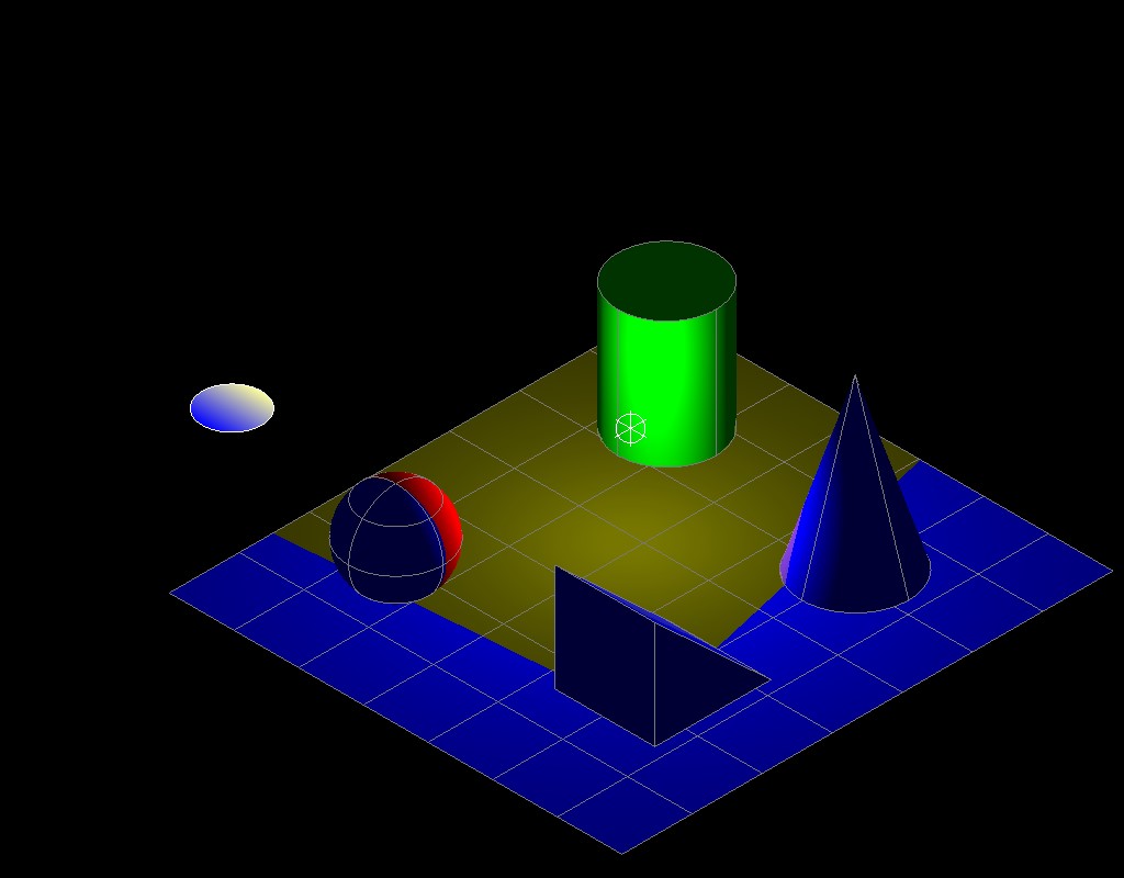
OdGiCuttedGeometryOutput 类继承自与 OdGiSectionGeometryOutput 类相同的基类 OdGiClippedGeometryOutput,因此方法几乎相同(除了 OdGiSectionGeometryOutput 类中与截面生成相关的一些附加标志)。至于截面生成,您可以覆盖任何特征数据(在此示例中我们使用了颜色和材质覆盖;我们使用蓝色而不是红色来表示切割几何体)。与截面几何体类似,我们可以覆盖几何体图元(如 shellProc 方法、polylineProc 方法等)来改变几何体输出行为,但与截面几何体不同的是,切割几何体接口可以接受任何类型的几何体图元,而不仅仅是壳和折线。
上述代码执行后,我们得到以下图像,其中生成了切割几何体(蓝色)而不是截面:
与截面几何体一样,切割几何体输出接口包含 OdGiCuttedGeometryOutput::setNonSectionableGeometryClipping 方法来控制不可截面几何体裁剪的行为。
请关注 ODA 博客,获取本系列的下一篇文章。
## 今天就开始行动
**免费试用 ODA 软件 60 天。
无风险,无需信用卡。**
[免费试用](https://www.opendesign.com/cn/free-trial)