[返回博客](/cn/blog) # 在 .dwg 文件中使用复合 .dgn 线型(第 1 部分,共 2 部分)
Andrew Markovich 四月 04, 2019 [\#dgn](/cn/blog/tag/dgn) [\#.dwg](/cn/blog/tag/dwg) [\#Example](/cn/blog/tag/example)
#### 简介
这是关于在 .dwg 数据库中创建复杂 .dgn 线型的系列文章的最后一篇。我们将利用之前文章中描述的关于创建 DGN 线型的知识,创建一个最终的复合线型,它将调用所有先前创建的线型组件。以下是供参考的先前文章:
- [在 .dwg 文件中使用 .dgn 线型(第 1 部分,共 4 部分)](https://www.opendesign.com/blog/2018/december/using-dgn-line-styles-dwg-file-part-1-4)
- [在 .dwg 文件中使用 .dgn 线型(第 2 部分,共 4 部分)](https://www.opendesign.com/blog/2019/january/using-dgn-line-styles-dwg-file-part-2-4)
- [在 .dwg 文件中使用 .dgn 线型(第 3 部分,共 4 部分)](https://www.opendesign.com/blog/2019/january/using-dgn-line-styles-dwg-file-part-3-4)
- [在 .dwg 文件中使用 .dgn 线型(第 4 部分,共 4 部分)](https://www.opendesign.com/blog/2019/february/using-dgn-line-styles-dwg-file-part-4-4)
#### 创建复合组件
复合线型组件可用于将两个或多个线型组件连接到单个复杂线型中。我们可以在新创建的复合组件中附加现有的笔划图案、内部、点和其他复合组件,设置它们之间的偏移,它们将作为一个复杂的线型一起绘制。就 .dwg 数据库而言,复合线型组件提供了与 OdDbMline 实体功能类似的功能,但 DGN 线型提供了许多附加功能。
要开始使用复合组件,请包含带有 OdDbLSCompoundComponent 类声明的头文件:
```
#include "DgnLS/DbLSCompoundComponent.h"
```
但首先我们需要其他现有组件的对象 ID,这些组件将附加到我们新创建的复合组件中。这里我们将使用先前文章中描述的现有组件,因此我们可以调用已经存在的功能:
```
// Declare commands from previous articles.
void _CreateDgnLineStyle_Stroke_func(OdEdCommandContext* pCmdCtx);
void _CreateDgnLineStyle_Internal_func(OdEdCommandContext* pCmdCtx);
void _CreateDgnLineStyle_Point_func(OdEdCommandContext* pCmdCtx);
```
只需调用它们即可将笔划图案、内部和点组件填充到 .dwg 数据库中:
```
// Create stroke, internal and point components
_CreateDgnLineStyle_Stroke_func(pCmdCtx);
_CreateDgnLineStyle_Internal_func(pCmdCtx);
_CreateDgnLineStyle_Point_func(pCmdCtx);
```
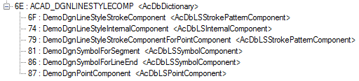
调用这些函数会将以下组件列表填充到 DGN 线型字典中:
由于我们没有从这些创建带有演示线型的 OdDbLine 实体的函数中删除测试代码,因此我们看到三条具有不同线型的线位于相同位置:
这当然不是复合线型。我们可以擦除这些线;它们不是未来操作所必需的。
现在我们可以提取先前创建的组件的对象 ID:
```
OdDbDictionaryPtr pLsDict = ::oddbDgnLSGetComponentsDictionary(pDb, OdDb::kForRead);
OdDbObjectId strokeCompId = pLsDict->getAt(OD_T("DemoDgnLineStyleStrokeComponent"));
OdDbObjectId internalCompId = pLsDict->getAt(OD_T("DemoDgnLineStyleInternalComponent"));
OdDbObjectId pointCompId = pLsDict->getAt(OD_T("DemoDgnPointComponent"));
OdDbObjectId pointStrokeCompId = pLsDict->getAt(OD_T("DemoDgnLineStyleStrokeComponentForPointComponent"));
```
“DemoDgnLineStyleStrokeComponent”由\_CreateDgnLineStyle\_Stroke\_func()函数调用创建。“DemoDgnLineStyleInternalComponent”由\_CreateDgnLineStyle\_Internal\_func()函数调用创建。“DemoDgnPointComponent”和“DemoDgnLineStyleStrokeComponentForPointComponent”由\_CreateDgnLineStyle\_Point\_func()函数调用创建。
现在我们可以创建复合组件本身。复合组件的创建与创建其他DGN线型组件非常相似:
```
// We need GUID for DgnLS objects
OdUInt8 dgnLS_UID[16];
::oddbDgnLSInitializeImportUID(dgnLS_UID);
// Create Compound LineStyle Component
OdDbLSCompoundComponentPtr pCompComponent = OdDbLSCompoundComponent::createObject();
pCompComponent->setComponentType(kLSCompoundComponent);
pCompComponent->setComponentUID(dgnLS_UID);
```
创建复合组件后,我们可以将四个现有线型组件的对象ID附加到它:
```
// Append compound component sub-components
pCompComponent->appendComponent(pointStrokeCompId);
pCompComponent->appendComponent(pointCompId);
pCompComponent->appendComponent(strokeCompId, -0.005);
pCompComponent->appendComponent(internalCompId, 0.005);
```
在此代码中,我们添加了点划线模式和点组件,没有偏移。划线模式和内部组件以0.005的偏移量添加到不同侧。
最后,我们可以将创建的复合组件附加到DGN线型字典:
```
// Add component into LineStyles dictionary
pLsDict->upgradeOpen();
pLsDict->setAt(OD_T("DemoDgnLineStyleCompoundComponent"), pCompComponent);
```
用于创建线型定义和.dwg线型表记录的代码与之前文章中的代码非常相似:
```
// Create LineStyle Definition
OdDbLSDefinitionPtr pLSDef = OdDbLSDefinition::createObject();
pLSDef->setComponent(pCompComponent->objectId());
pLSDef->setComponentUID(pCompComponent->componentUID());
// Create Linetype Table Record
OdDbLinetypeTableRecordPtr pLtpRec = OdDbLinetypeTableRecord::createObject();
pLtpRec->setName(OD_T("DemoDgnLineStyleCompound"));
pLtpRec->setComments(OD_T("Compound component"));
OdDbObjectId lsId = OdDbLinetypeTable::cast(pDb->getLinetypeTableId().safeOpenObject(OdDb::kForWrite))->add(pLtpRec);
// Attach LineStyle Definition to Linetype Table Record
pLtpRec->createExtensionDictionary();
OdDbDictionaryPtr pLtpDict = OdDbDictionary::cast(pLtpRec->extensionDictionary().openObject(OdDb::kForWrite));
pLtpDict->setAt(::oddbDgnLSGetDefinitionKeyName(), pLSDef);
```
我们可以填充一些OdDbLine实体:
```
// Create three lines for LineStyle testing
OdDbObjectId lineIds[3];
for (int nLine = 0; nLine < 3; nLine++)
{
OdDbLinePtr pLine = OdDbLine::createObject();
pLine->setDatabaseDefaults(pDb);
pLine->setLinetype(lsId);
pLine->setStartPoint(OdGePoint3d(1.1, 0.03 - 0.03 * nLine, 0.0));
pLine->setEndPoint(OdGePoint3d(1.2, 0.03 - 0.03 * nLine, 0.0));
lineIds[nLine] = OdDbBlockTableRecord::cast(pDb->getActiveLayoutBTRId().safeOpenObject(OdDb::kForWrite))->appendOdDbEntity(pLine);
}
```
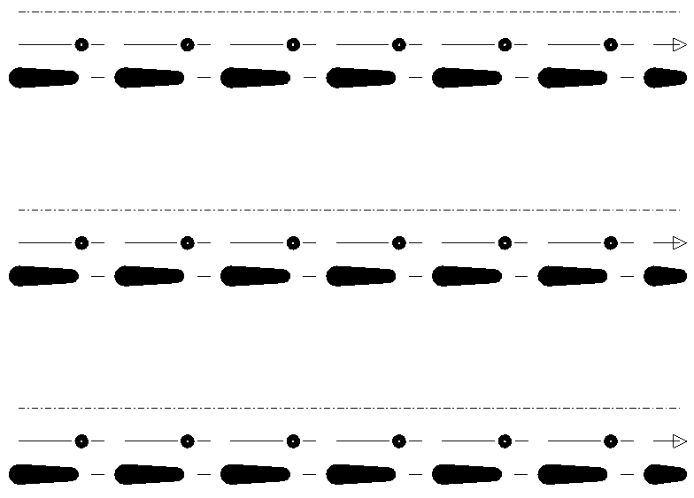
由上述代码创建的最终图片如下所示:
更仔细地考虑创建的复合线型:
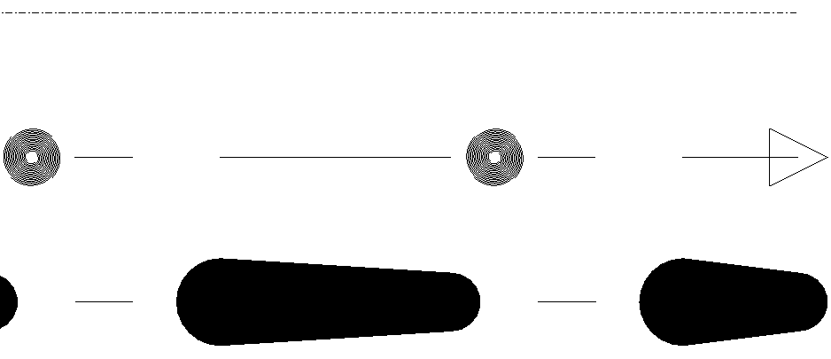在这里,我们可以在线型的第一行(偏移量0.005)看到内部组件,在中心看到点和点划线模式组件,在线型的最后一行(偏移量-0.005)看到带有宽度且位于其中一个虚线段上的划线模式组件。实际上,添加到复合组件的线型组件的侧面取决于曲线方向。在我们的演示中,我们创建了一条从左到右的线,因此最终我们展示了线型组件的顺序。
本系列的下一篇文章将描述可应用于特定实体的线型修改器。
## 今天就开始行动
**免费试用 ODA 软件 60 天。
无风险,无需信用卡。**
[免费试用](https://www.opendesign.com/cn/free-trial)