[返回博客](/cn/blog) # 创建 NURBS 曲线
Vladimir Savelyev 五月 17, 2018 [\#rendering](/cn/blog/tag/rendering) [\#Example](/cn/blog/tag/example) [\#getting started](/cn/blog/tag/getting-started)
使用 Teigha,您可以使用 Teigha Ge 库及其类 OdGeNurbCurve2d 和 OdGeNurbCurve3d 创建非均匀有理 B 样条 (NURBS) 曲线。
让我们考虑曲线的 3D 版本(2D 曲线具有相同的行为)。NURBS 曲线由其阶数、一组加权控制点和节点向量定义。可以使用构造函数将此数据设置为曲线:
```
OdGeNurbCurve3d(
int degree,
const OdGeKnotVector& knots,
const OdGePoint3dArray& controlPoints,
const OdGeDoubleArray& weights,
bool isPeriodic = false);
```
但这只是描述 NURBS 的“核心”数学数据;使用它来创建您可能需要的形状并不直观。另一种选择是使用拟合数据创建 NURBS。这是设置拟合数据的构造函数:
```
OdGeNurbCurve3d(
const OdGePoint3dArray& fitPoints,
const OdGeVector3d& startTangent,
const OdGeVector3d& endTangent,
bool startTangentDefined = true,
bool endTangentDefined = true,
const OdGeTol& fitTol = OdGeContext::gTol);
```
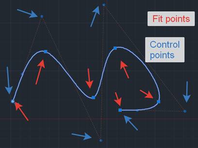
这里我们使用 fitPoints,它们是曲线将经过的插值点。这意味着拟合点在曲线上。下图显示了拟合点和控制点之间的区别:
起点和终点切线是定义曲线两端切线的向量。您不能通过将相应的标志设置为“false”来定义它们。拟合容差是曲线可能偏离拟合点的距离。默认情况下,它为零,曲线精确地穿过所有拟合点。下图显示了这些参数的影响:
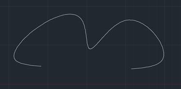未定义终点切线
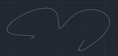已定义终点切线
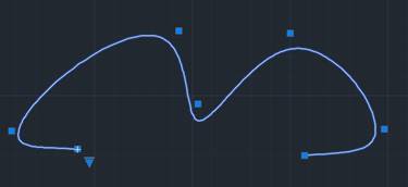已定义拟合容差,曲线经过拟合点‘附近’
您还可以创建 NURBS,其拟合点在每个拟合点处定义一个切线。使用以下构造函数:
```
OdGeNurbCurve3d(
const OdGePoint3dArray& fitPoints,
const OdGeVector3dArray& fitTangents,
const OdGeTol& fitTolerance = OdGeContext::gTol,
bool isPeriodic = false);
```
即使曲线最初是使用控制点和节点创建的,您也可以创建拟合数据来使用;请使用 buildFitData 函数。
出于数据库目的,您也可以使用 OdDbSpline 类来表示 3D NURBS 曲线。您可以创建所需形状的 OdGeNurbCurve3d 曲线,并使用 setFromOdGeCurve 方法将其设置为 OdDbSpline 类。
## 今天就开始行动
**免费试用 ODA 软件 60 天。
无风险,无需信用卡。**
[免费试用](https://www.opendesign.com/cn/free-trial)